Rule 4123:1-21-04 | Automotive fire apparatus.


(A) New automotive fire appartaus shall meet the requirements of the applicable NFPA Standards: "NFPA 1901, 2013 Edition, Standard for Automotive Fire Apparatus; NFPA 1906, 2013 Edition, Standard for Wildland Fire Apparatus; NFPA 1917, 2013 Edition, Standard for Automotive Ambulances."
(1) Two copies of a complete operation and maintenance manual covering the completed apparatus, including but not limited to the truck, pump, wiring and piping diagrams, lubrication charts, operating instructions for the chassis, any major component such as pump or aerial device or other fire fighting equipment; precautions related to multiple configurations of aerial devices; instructions regarding the frequency and procedure for recommended maintenance; and parts replacement information, shall be available. Also, all manufacturers' operations and maintenance documents supplied with components and equipment that are installed by the contractor shall be supplied and made available.
(B) GAWR, GCWR, and GVWR adequate to carry a full water tank, other tanks full the specified hose load, ground ladders and a personnel weight and miscellaneous equipment allowance shall be provided on the apparatus.
(C) Automatic engine shutdown systems are prohibited unless they are an integral part of the standard engine management system, which cannot be disabled.
(D) An engine speed control device shall be installed to allow an increase in the engine speed when the apparatus is parked. An interlock shall prevent the operation of this engine speed control device unless the parking brake is fully engaged and the transmission is in neutral or park, or the parking brake is engaged and the engine is disengaged from the drive wheels.
(E) Fuel system, gasoline or diesel.
(1) The fuel line(s) shall be so located or protected as not to be subjected to excessive heating from any portion of a vehicle exhaust system. The line(s) shall be protected from mechanical injury.
(2) Fuel tank and fill piping shall be so placed as to be protected from mechanical injury and shall not be exposed to heat from exhaust or other source of ignition.
(3) The tank fill opening shall be marked with a label indicating the proper fuel.
(F) Exhaust system, gasoline or diesel.
(1) The exhaust piping and discharge outlet shall be so located as not to expose any portion of the apparatus or equipment to excessive heating.
(2) Exhaust pipe discharge shall not be directed toward any operator's position.
(3) Silencing devices shall be provided.
(4) When parts of the exhaust system are exposed to operating personnel, protective guards shall be provided.
(5) If the apparatus is equipped with stabilizers, the exhaust piping discharge shall be directed away from the contact area between the stabilizer and the ground when the stabilizer is deployed.
(G) Low voltage (twelve/twenty-four volt) electrical system and warning devices.
(1) All electrical circuit wiring shall be made with stranded conductors of a carrying capacity of one hundred twenty-five per cent of the anticipated maximum circuit loading. Insulation shall be in accordance with the recommended standards of the society of automotive engineers for such loading at the potential employed. Overall covering of conductors shall be of the moisture-resistant type and have a minimum continuous temperature rating of one hundred ninety-four degrees Fahrenheit (ninety degrees Celsius). All connections shall be made with lugs or terminals mechanically secured to the conductors. Wiring shall be restrained to prevent damage caused by chafing or ice buildup, and protected against heat, liquid contaminants, or other environmental factors.
(2) Circuits shall be provided with overload protective devices. Such devices shall be readily accessible and protected against heat, physical injury, and water spray.
(3) Power supply.
(a) A twelve volt or greater electrical alternator shall be provided. It shall have a minimum output at idle to meet the minimum continuous electrical load of the apparatus as defined in NFPA 1901 at two hundred degrees Fahrenheit (ninety-three degrees Celsius) ambient temperature within the engine compartment, and shall be provided with full automatic regulation.
(b) The condition of the low-voltage electrical system shall be monitored by a system that provides an audible and visual warning to the driver or operator of the apparatus.
(c) A voltmeter shall be mounted on the driver's instrument panel to allow direct observation of the system voltage.
(d) If the total continuous electrical load exceeds the minimum continuous electrical output rating of the installed alternator(s) operating under the conditions specified in paragraph (G)(3)(a) of this rule, an automatic electrical load management system shall be required.
(4) Batteries.
Batteries shall be securely mounted and protected against physical injury and vibration, water spray, and engine and exhaust heat. When an enclosed battery compartment is provided, it shall be adequately ventilated, and the batteries shall be readily accessible for examination, test, and maintenance.
(5) Lights and warning devices.
(a) The rear stop, tail, and directional lights shall be so mounted that they will not be obscured by equipment carried on the rear step. Turn signals shall be visible from front, sides, and rear. On apparatus thirty feet or longer in length, a turn signal shall be mounted approximately midway along the apparatus at approximately running board height.
(b) All apparatus shall have upper and lower optical warning devices. The upper and lower warning levels shall each be divided into four warning zones. The four zones shall be determined by drawing lines through the geometric center of the apparatus at forty-five degrees to a line lengthwise of the apparatus through the geometric center. The four zones shall be designated A, B, C, and D in a clockwise direction with zone A to the front of the apparatus (see figure 1).
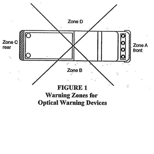
(i) The front optical warning devices shall be placed so as to maintain the maximum possible separation from the headlights.
(ii) A midship optical warning device shall be mounted on both the right and left sides of the apparatus with the optical center of the device at a distance between eighteen and sixty-two inches above level ground if the distance between the front and rear lower-level optical devices exceeds twenty-five feet.
(c) Apparatus shall have hooded lights, with individual switches, providing illumination of the pump operating panel, tool and equipment compartments, steps, and walkways. Switches shall be located within easy reach of the operator.
(d) The work area immediately behind the vehicle shall be illuminated to a level of at least three footcandles (thirty lux) within a ten feet by ten feet square to the rear of the vehicle. If a hose bed is provided, lighting on this hosebed shall be at a level of three footcandles (thirty lux) or higher.
(e) The apparatus shall be equipped with lighting that is capable of providing illumination at a minimum level of two footcandle ( twenty lux) on the ground area within thirty inches of the edge of the apparatus in areas designed for personnel to climb onto or descend from the apparatus to the ground level. Lighting designed to provide illumination on areas under the driver and crew riding area exits shall be activated automatically when the exit doors are opened. All other ground area lighting shall be switchable.
(f) A red flashing or rotating light, located in the driving compartment, shall be illuminated automatically whenever the apparatus's parking brake is not fully engaged and any of the following conditions exist:
(i) Any passenger or equipment door is open.
(ii) Any ladder or equipment rack is not in the stowed position.
(iii) Stabilizer system not in its stowed position.
(iv) Powered light tower is extended.
(v) Any other device is opened, extended, or deployed that creates a hazard or is likely to cause damage to the apparatus if the apparatus is moved.
The light shall be marked with a sign that reads: "Do Not Move Apparatus When Light is On."
(g) Audible warning equipment in the form of one automotive horn and one electric or electronic siren shall be provided. Control for operating the siren shall be provided for the right and left seat positions.
(h) Where furnished, air horns, electric siren(s), and electronic siren speaker(s) shall be mounted as low and as far forward on the apparatus as practical. Audible warning equipment shall not be mounted on the roof of the apparatus.
(i) An electric or electronic backup alarm shall be provided that meets the type D (87 dBa) requirements of SAE J994, 2009 edition.
(H) Vehicle components.
(1) Line voltage (one hundred ten/two hundred twenty volts).
(a) The generating system shall be installed in accordance with the grounding requirements of Section 250-34 of NFPA 70, 2014 edition, "National Electric Code."
(b) When receptacles or other facilities providing one hundred ten volt AC or DC power are installed, such receptacles and other facilities shall be of the weatherproof type, and all circuits or associated wiring shall have at the source of one hundred ten volt supply overload protection rated at the carrying capacity of the conductor. Circuits shall be three-wired and installed in accordance with Section 250-34 of NFPA 70, "National Electric Code." Those receptacles shall conform to the appropriate NEMA configuration for the voltage and capacity of the circuit.
(c) All fixed auxiliary engine-driven generators shall comply with article 445, "Generators," of NFPA 70, NEC.
(i) They shall be installed so that fumes, vapors, heat, and vibrations do not enter the interior passenger compartment. They also shall have the exhaust outlet piped to the exterior and located so that exhaust is directed away from any operator's position.
(ii) Where parts of the exhaust system are exposed so that they can cause injury to operating personnel, protective guards shall be provided.
(d) Portable generator installations shall comply with article 445, "Generators," of NFPA 70, NEC.
(e) If the apparatus is equipped with a fixed power inlet (shoreline inlet), it shall be a permanently mounted, flanged surface inlet (male-recessed-type receptacle with cover) sized in accordance with the anticipated load and wired directly to the system or device to be powered; or wired to a transfer switch to isolate one power source from the other where a circuit(s) is intended to be supplied from more than one power source.
(i) The apparatus shall have a label permanently affixed at the power inlet that indicates the following:
(a) Shore power inlet.
(i) Type of line voltage (manufacturer to insert specific voltage of one hundred twenty/two hundred forty, AC/DC).
(ii) Current rating in amps (manufacturer to insert specific amp rating).
(2) Braking system.
(a) Apparatus shall be equipped with an all-wheel antilock braking system if such system is available from the chassis manufacturer.
(b) Service and parking brakes shall be independent and separate systems. All brakes shall be readily accessible for adjustment.
(c) The service brake application valve, when applied, shall operate all the service brakes on the vehicle or combination of vehicles.
(d) Parking brakes shall control the rear wheels, or all wheels, and shall be of a positive, mechanically actuated type with provision for securely holding in position when applied. The parking brake system shall hold the fully loaded apparatus on at least a twenty per cent grade. Neither a lock-up device to retain applied pressure on hydraulically actuated service brake system nor a "park" position on an automatic transmission as a substitute for a separate parking brake system is acceptable.
(e) Where air-actuated braking systems are provided, they shall include the following:
(i) An automatic moisture ejector;
(ii) An air dryer;
(iii) A pressure protection valve to prevent the use of all air-operated accessories except air-operated windshield wipers and air-assist steering, if provided, when the system air pressure drops below eighty psi (five hundred fifty kPa);
(iv) A quick buildup section in the air reservoir system arranged so that if the apparatus has a completely discharged system, it is able to move within sixty seconds of startup.
(a) The quick buildup system shall provide sufficient air pressure so that the apparatus has no brake drag and is able to stop under the intended operating conditions following the sixty second buildup time.
(b) On a chassis that cannot be equipped with a quick buildup air brake system, an onboard automatic electric compressor or a fire station compressed air shoreline hookup shall be permitted in order to maintain full operating air pressure while the vehicle is not running.
(f) Two or more wheel chocks, mounted in readily accessible locations, that meet or exceed the requirements of SAE J348, 1990 edition, "Standard for Wheel Chocks," for the wheel diameter on which the chocks are to be used, shall be provided and used when the apparatus is not being driven but being operated in a stationary position.
(g) Service brakes shall be capable of bringing a fully laden apparatus to a complete stop from an initial speed of twenty mph in a distance not exceeding thirty-five feet by actual measurement on a substantially hard surface road that is free from loose material, oil, or grease.
(3) Suspension and wheels.
(a) Each load-bearing tire and rim of the apparatus shall carry a weight not in excess of the tire manufacturer's rating.
(b) An angle of approach and an angle of departure of at least eight degrees shall be maintained at the front and rear of the vehicle when normally loaded.
(c) Fenders and guards shall be braced and firmly secured.
(d) The steering mechanism for front axles shall be capable of turning the front wheels to an angle of at least twenty-eight degrees front axles and thirty degrees for nondriving front axles to both right and left. Power or power-assisted steering shall be provided.
(4) Body.
(a) A bumper shall be provided on the front of the chassis, and the bumper mounting brackets shall be attached to the frame.
(b) Holders, boxes, compartments, or other attachments shall be provided for all tools, equipment, play-pipes, and other items on the apparatus. Equipment holders shall be firmly attached and designed so that equipment will remain in place under all running conditions but be quickly removable for use.
(c) Steps, platforms, or secure ladders shall be provided so that fire fighters have access to all working and storage areas of the apparatus. The maximum stepping height shall not exceed eighteen inches with the exception of the ground to first step. When the ground to first step, platform, or ladder rung exceeds twenty-four inches, a permanently attached supplemental means of access/egress from the ground to these steps, platforms, or secure ladders shall be provided. The supplemental access means shall consist of step(s), platform(s), or ladder(s). The ground to first step height shall be determined with the apparatus on level ground. When the apparatus is supplied with stabilizers, the ground to first step height shall be determined with the apparatus on level ground and the stabilizers deployed according to the manufacturer's instructions.
(i) All steps, platforms, or ladders shall be capable of sustaining a minimum static load of five hundred pounds without deformation.
(ii) All exterior surfaces designated as stepping, standing, and walking areas shall have a minimum average slip resistance of 0.68 in accordance with ASTM F 1679. All interior steps shall provide an average minimum slip resistance of 0.52. Where the fuel fill is located at or near a stepping surface, the surface shall be constructed of an open grate-type material.
(iii) All steps shall have a minimum area of thirty-five square inches and be arranged to provide at least eight inches of clearance between the front of the step and any obstruction. All ladders shall have at least eight inches of clearance between any rung and the body of the apparatus.
(d) Access handrails shall be provided at all entrances to the driving or crew compartment and at any location where the fire fighter is required to climb up on the apparatus for access to equipment. Exterior access handrails shall be constructed of a slip-resistant, non-corrosive material. Rails shall be between one inch and one and five-eights inches in diameter and have a minimum clearance between the rails and any surface of at least two inches. All rails shall be designed and mounted to reduce the possibility of hand slippage and to avoid snagging of hose, equipment, or clothing.
(e) A reflective stripe(s) shall be affixed to the perimeter of the apparatus. The stripe or combination of stripes shall be a minimum of four inches in total width and shall conform to the minimum requirements of ASTM D 4956, 2013 edition. At least fifty percent of the cab and body length on each side, at least fifty percent of the width of the rear, and at least twenty-five percent of the width of the front of the apparatus shall have the reflective material affixed to it. A graphic design meeting the reflectivity requirements of this paragraph shall be permitted to replace all or part of the required striping material if the design or combination thereof covers at least the same perimeter length(s) required within.
(5) Driving and crew compartment.
(a) A fully enclosed driving or crew compartment with seating for no fewer than two persons shall be provided. Seat belts shall be provided and shall be utilized by each occupant of the cab.
(b) In wildland fire fighting, employees shall be required to ride within a fully enclosed personnel area.
(c) The noise in the compartment shall not be in excess of ninety dBA without any warning devices in operation and while the vehicle is traveling at a steady speed of forty-five mph on a level, hard, smooth surface road.
(d) All interior crew and driving compartment door handles shall be designed and installed to protect against accidental or inadvertent opening.
(e) Head height at any suspension-style seat shall be at least thirty-seven inches from the seat H-point to the ceiling. For nonsuspension-style seats it shall be thirty-five inches. Each seating space shall have a minimum width of twenty-two inches at the shoulder level. Seat cushions shall be a minimum of eighteen inches in width and fifteen inches from the front of the cushion to the face of the seat back. A back cushion that extends from the face of the seat vertically at least eighteen inches and that is a minimum of eighteen inches wide shall be provided. The back cushion shall be permitted to be split to accommodate a fully recessed SCBA and bracket. Where the back cushion is split, a headrest shall be supplied.
(f) Where SCBA units are mounted within the crew compartment, a positive, mechanical means of holding the SCBA in its stowed position shall be provided. The bracket holding device and its mounting shall retain the SCBA unit when subjected to a nine-G force and shall be installed in accordance with the bracket manufacturer's requirements. If the SCBA cylinder is mounted in a vertical position with the valve down, it shall be supported with a brace or yoke under the cylinder or valve area to prevent downward movement.
(g) All equipment within the driving or crew area, shall be securely fastened. All equipment not required to be used during an emergency response, with the exception of SCBA units shall be contained in a fully enclosed and latched compartment, or mounted in a bracket(s) that is capable of containing the contents when a nine-G force is applied in the longitudinal axis of the vehicle or a three-G force is applied in any other direction.
(h) The driver's seat shall be readily adjustable by the driver.
(i) Where the crew compartment and the driving compartment are separated, prohibiting direct voice communication, a two-way voice communication system shall be provided.
(j) A speedometer/odometer shall be provided.
(k) All driving and crew compartment doors shall have at least ninety-six square inches of reflective material affixed to the inside of each door.
(l) The apparatus shall have sufficient lighting to provide an average level of two footcandle (twenty lux) in the driving and crew compartments.
(m) Each engine compartment and pump compartment shall have a light of at least twenty candlepower (two hundred fifty lumens).
(6) Tractor-drawn vehicles.
(a) A tractor-drawn vehicle shall consist of a tractor with a permanent, non-kingpinned "fifth wheel" mounted upon the rear of the chassis to carry the forward end of the aerial ladder trailer unit. The fifth wheel and body design shall be of a type that permits full ninety degree jackknifing of the tractor-trailer combination with the stabilizers in the stored position.
(b) A tiller steering wheel shall be provided to steer the rear wheels of the trailer unit. The steering shall be of the power or power-assisted type.
(c) A fully enclosed tiller driving compartment with seating for one person shall be provided at the rear wheel's steering position. Tiller seats shall have a lap belt.
(d) A control at the tiller driver's position shall be provided to prevent starting of the engine if the tiller driver is not in place.
(e) A two-way voice communication system shall be provided for communication between the drivers.
(f) A heater or ventilation system, a defroster, and a windshield wiper and washer shall be provided.
(g) The following instrumentation and controls shall be mounted in the tiller driving compartment and shall be clearly identified and visible to the driver while seated:
(i) Heater/defroster controls;
(ii) Turn signal indicator lights;
(iii) Starter control;
(iv) Windshield wiper control.
(h) Mirrors that provide side and rear visibility shall be provided on both sides of the tiller enclosure.
(i) If the sides of the trailer are not visible from the tiller seat, a device shall be installed as a point of reference for the tillerman to judge clearance distance.
(j) If the manufacturer's design requires that the load from the aerial device not be transferred to the rear springs of the tractor, a device shall be installed that will prevent such a weight transfer.
(I) Pumps.
(1) Construction.
(a) The pump shall be designed and constructed to withstand a hydrostatic test of five hundred psig minimum for ten minutes. A certificate documenting this test shall be furnished.
(b) When an auxiliary pump is provided in combination with an attack pump and when the pumps are interconnected so that pressure from one pump may be transmitted to the other pump, check valves, intake and/or discharge relief valves, pump drive gear ratios, or other automatic means shall be provided to avoid pressurizing either pump beyond its maximum rated hydrostatic pressure.
(c) The entire discharge and intake piping system, valves, drain cocks and lines, and intake and outlet closures, excluding the tank fill and tank to pump lines on the tank side of the valves in those lines, shall be designed for five hundred psig.
(2) Pump intake and discharge.
(a) Where a three-inch or larger intake or discharge valve is provided, except the tank to pump intake, the valve mechanism shall be slow-operating to permit changing the position of the flow regulating element of the valve from full close to full open, or vice versa.
(b) Each gated intake or discharge shall be equipped with a three-fourths-inch bleeder valve located in close proximity to the intake or discharge to bleed off air or water from a hose connected to the intake or discharge. The valve shall be operational without the operator's having to get under the apparatus. If a siamese is attached to an intake, it shall be equipped with a three-fourths-inch bleeder valve on each inlet.
(c) An adjustable two-and-one-half-inch or larger intake pressure relief system shall be permanently installed. The system shall be designed to self-restore automatically to a nonrelieving position when excessive pressure is no longer present. The minimum range of pressure adjustment shall permit control of the intake pressure relief point from ninety psi to at least one hundred eighty-five psi.
(3) Pump controls.
(a) Adequate illumination shall be provided for all gages and controls located at the pump operator's position.
(b) All markings required at the pump operator's position shall be permanent, capable of withstanding the effects of extremes of weather and temperature, and securely attached.
(c) Provisions shall be made for quickly and easily placing the pump in operation. The lever or other device shall be marked to indicate when it is correctly positioned for pumping.
(d) Any control device used in the pumping system power train between the engine and pump shall be equipped with a means to prevent unintentional movement of the control device from its set position.
(e) A nameplate indicating the chassis transmission shift selector position to be used for pumping shall be provided in the cab and located so that it can be easily read from the driver's position.
(f) When the pump is driven by a split shaft PTO, an indicator light shall be located in the driving compartment. This indicator light shall be energized when the pump shift has been completed and shall be labeled "Pump Engaged." When an automatic chassis transmission is provided, a second indicator light in the driving compartment and an indicator light located at the pump operator's position shall be provided and energized when the pump shift has been completed, the chassis transmission is engaged in pump gear and the parking brake engaged. The light in the driving compartment shall be labeled "OK to Pump." The light on the pump operator's panel shall be positioned adjacent to and preferably above the throttle control and shall be labeled: "Throttle Ready."
(g) When an automatic or manual chassis transmission is provided and when the pump is driven by a transmission mounted (SAE) PTO, front-of-engine crankshaft PTO, or engine flywheel PTO and is used for stationary pumping with the chassis transmission in neutral, or is used for pump and roll with the chassis transmission in any forward or reverse gear, shift indicator lights shall be provided as required in paragraphs (H)(3)(g)(i) and (H)(3)(g)(ii) of this rule.
(i) There shall be two indicator lights in the driving compartment. One of the lights shall be energized when the pump drive has been engaged and shall be labeled "Pump Engaged." The second light shall be energized when both the pump drive has been engaged the chassis transmission is in neutral and the parking brake engaged and shall be labeled "OK to Pump."
(ii) For pump-and-roll apparatus, an additional "OK to Pump and Roll" indicator light shall be provided in the driving compartment and shall be energized when the pump is engaged, the chassis transmission is on road gear, and the parking brake is released. When the "OK to Pump and Roll" indicator is energized, the "OK to Pump" indicator shall not be energized.
(iii) A "Throttle Ready" indicator shall be provided at the pump operator's panel that is energized when the "OK to Pump" indicator is energized, or when the chassis transmission is neutral, and the parking brake is engaged.
(h) With parallel-series centrifugal pumps, the control positions for parallel operation (volume) and series operation (pressure) shall be clearly indicated. The control for changing the pump from series to parallel and vice versa shall be operable at the pump operator's position.
(i) Means shall be provided for controlling pressure at the pump either through an automatic relief valve or a pressure regulator controlling the speed of the pump. The device shall be capable of operation over a range of ninety to three hundred psig discharge pressure and shall limit the pressure rise upon activation to a maximum of thirty psi. A relief valve shall be equipped with an amber light that indicates when the valve is open. A pressure regulator shall be equipped with a green light that indicates when the regulator is activated. The means provided shall be controllable by one person in the pump operator's position.
If the system discharges water to the atmosphere, the discharge shall be in a manner that will not expose personnel to high-pressure water steams.
(4) Engine controls.
A throttle control that will hold its set position shall be provided to control the engine speed and located not higher that seventy-two inches nor lower than forty-two inches from the pump operator's position with all instrumentation in full view.
(J) Tanks.
(1) All water tanks shall be constructed of noncorrosive material or other materials that are protected against corrosion and deterioration. The water tanks shall have a means to permit flushing of the tank.
(2) Tanks shall be securely fastened and cushioned or cradled to avoid stress when the apparatus is traveling over uneven terrain.
(3) Tanks shall be provided with at least one swash or baffle partition. Each tank shall have a sufficient number of swash partitions so that the maximum dimension of any space in the tank, either transverse or longitudinal, shall not exceed forty-eight inches.
(4) The overflow outlet on water tanks shall be designed so that, while the vehicle is in motion, the overflow shall direct any water behind the rear axle so as not to interfere with rear tire traction.
(5) Pressure vessel foam concentrate or foam solution tanks.
(a) The tank shall be of welded construction and designed, fabricated, and stamped in accordance with the requirements of the ASME "Boiler and Pressure Vessel Code, 2015 Edition" Section VIII, Division I, for the required pressure. All pressure tanks and associated piping shall be designed to a minimum of one and one-half times working pressure.
(b) The pressure vessel tank shall be protected against corrosion from the foam concentrate stored in the tank.
(c) The fill cap shall be equipped with non-tapered threads and a compressible gasket.
(d) A safety vent hole shall be located in the fill cap so that it will vent the tank pressure while at least three and one-half threads are still engaged.
(e) A minimum one-half inch valved vent shall be provided on all pressure vessel tanks.
(f) An approved ASME relief valve, properly set, shall be provided on the tank to prevent tank pressure from exceeding one hundred ten per cent of the maximum allowable working pressure.
(g) A device indicating the internal pressure of the pressure vessel shall be provided and located at the operator's position.
(h) A minimum one inch inside diameter full flow drain valve and piping shall be provided on all pressure vessel tanks.
(6) Compressed air source.
(a) Holding, surge, or separator tanks (DOT tank or ASME pressure vessel) shall comply with 29 CFR 1910.169, 2007 edition, "Air Receivers." or equal for the rated pressure.
(b) Transportable air tanks shall comply with 49 CFR 178.37, 2006 edition, "Specification 3AA and 3AAX, Seamless Steel Cylinders" or 29 CFR 1910.169, 2007 edition, "Air Receivers."
(c) Relief valves on transportable air tanks shall be of the ASME type on ASME cylinders and of the DOT type on DOT cylinders or equal for the rated pressure.
(d) Cylinders shall be securely mounted on the apparatus so that they will not shift during normal apparatus driving and operation.
(e) Valves installed on air tanks shall meet the requirements of the compressed air association or equivalent standards regarding pressure and usage with compressed air.
(f) The compressed air system shall be equipped with an air pressure relief valve which is set to prevent the compressed air system from exceeding one hundred ten percent of the maximum allowance working pressure of the system. The outlet of the relief device shall be routed to an area that does not expose personnel to air blasts or cause the creation of dust.
(g) If the installation utilizes cylinders that require periodic testing, a label shall be placed on the operator's panel indicating the test date stamped on the cylinders and the date the cylinders will next require testing.
(K) Water towers.
(1) If the water tower is equipped with a ladder attached to the boom or sections for continuous egress, the ladder shall meet the requirements for aerial ladders in paragraphs (L)(1)(a) to (L)(1)(g) of this rule.
(2) If the water tower is rated in multiple configurations, these configurations, including the rated load capacity of each, shall be clearly described in the operations manual and on the sign at the operator's station.
(3) Operating mechanisms.
(a) Power-operated elevating and extending devices shall be provided. They shall be so designed and provided with adequate power to allow multiple movements of the water tower booms or sections simultaneously under all rated conditions of loading. An automatic locking device(s) shall be provided so that the desired elevated position can be maintained. Provisions shall be made to prevent damage at top and bottom limits.
(b) A lock shall be provided that will retain the water tower booms or sections in the bed when the vehicle is in motion.
(c) A power-operated turntable shall be provided that will permit continuous rotation in either direction under all the rated conditions of loading. The turntable rotation bearing shall be accessible for lubrication and retorquing of bolts.
(d) The turntable rotation mechanism shall be provided with an automatically applied brake or self-locking drive. It shall provide braking capacity with all power systems nonfunctioning to prevent turntable rotation under all rated conditions of loading.
(4) Stabilization.
(a) The water tower shall be capable of sustaining a static load of one and one-half times its rated capacity in every position in which the water tower can be placed when the vehicle is on a firm and level surface with all normally removable items, such as water hose, ground ladders, loose equipment, etc., removed. If having stabilizers extended to firm footing is part of the definition of the configuration, they shall be extended for the purpose of determining whether the vehicle meets this stability requirement.
(b) The water tower shall be capable of sustaining a static load of one and one-third times its rated capacity in every position in which the water tower can be placed when the vehicle is on a slope of five degrees downward in the direction most likely to cause overturning. If having the stabilizers extended to a firm footing is part of the definition of the configuration, they shall be extended to provide leveling for the purpose of determining whether the vehicle meets this stability requirement. If other facilities, such as a means of turntable leveling, are provided to minimize the effect of the sloping surface, then those facilities may be utilized for the purpose of determining whether the vehicle meets this stability requirement.
(c) If stabilizers are power-operated, the controls shall be arranged so that the operator may view the stabilizers in motion. An audible alarm of no less than eighty-seven dBA shall sound when a stabilizer is moving.
(d) The ground contact area for each stabilizer shall be such that a unit pressure of no greater than seventy-five PSI will be exerted over the ground contact area when the apparatus is fully loaded and the water tower is carrying its rated capacity in every position allowed by the manufacturer This shall be permitted to be accomplished with stabilizer pads in conjunction with the permanently mounted stabilizer shoes to meet the loading requirement of seventy-five psi. The stabilizer shoe shall be capable of swiveling in at least one direction. If the shoe swivels in one direction only, it shall swivel on an axis parallel to the longitudinal axis of the apparatus..
(e) All stabilizers that protrude beyond the body of the apparatus shall be striped or painted with reflective material to indicate a hazard or obstruction and shall be provided with at least one red warning light visible on the side of the vehicle where the stabilizer is located.
(5) Control devices.
(a) Controls shall be provided at the driver's position to transfer power to the water tower. A visual signal shall be provided at the driver's position to indicate when the operating mechanisms are engaged.
(b) An interlock shall be provided that prevents operation of the water tower until the parking brakes have been set and the transmission has been placed in neutral or the transmission is in the drive position with the drive line to the rear axle disengaged.
(c) An interlock shall be provided that allows operation of the engine speed control only after the parking brakes have been set and the transmission is in neutral.
(d) An interlock system shall be provided to prevent the lifting of the water tower from the travel position until all the stabilizers are in a configuration to meet the stability requirements of paragraphs (K)(4)(a) to (K)(4)(e) of this rule. The interlock system shall also prevent the moving of the stabilizers unless the water tower is in the travel position.
(e) A water tower operator's position shall be provided on the apparatus so that the operator is not in contact with the ground. If equipped with a pump, provisions shall be made so that the pump operator is not in contact with the ground. Sign(s) shall be placed to warn the operator(s) of electrocution hazards.
(f) All controls shall be lighted, clearly marked, and located within easy reach of the operator.
(g) Means shall be provided to prevent unintentional movement of the water tower.
(h) Controls shall be arranged so that each control can be operated by an operator with a gloved hand without disturbing any other control.
(i) When a three lever system is used to control the basic functions of the water tower, the levers shall be distinctively different from the other controls on the panel and arranged adjacent to each other with the extension control being the left lever, the rotation control being the center lever, and the elevation control being the right lever.
(j) The water tower shall extend when the extension control is pushed up or forward (away from the operator).
(k) If the rotation control has a forward/backward orientation or an up/down orientation, the turntable shall rotate clockwise when the rotation control is pushed up or forward (away from the operator). Otherwise, the rotation control handle shall move in the direction of rotation.
(l) The water tower shall lower when the elevation control is pushed up or forward (away from the operator).
(m) All controls regulating movement of the aerial device shall automatically return to the neutral position upon release.
(n) Indicating devices, lighted, clearly marked, and conveniently arranged, shall be visible from the operator's position to:
(i) Indicate that rungs are aligned for climbing, if applicable;
(ii) Indicate the alignment of the boom or sections with the travel bed;
(iii) Indicate elevation, extension, and capacity ratings or provide an equivalent load indicating system.
(o) If the water tower incorporates a ladder, a second control station shall be provided near the water tower nozzle, accessible to personnel on the ladder for control of all nozzle functions.
(p) If a second control station is provided at the water tower nozzle, a weather-resistant, two-way voice communication system shall be provided between the water tower operator's control stations and the control station at the nozzle. The speaker/microphone at the nozzle control station shall allow for hands-free operation.
(6) Safety.
(a) If the operator's position is on the turntable, the turntable platform shall be provided with a railing no less than forty-two inches high The railing design shall be capable of withstanding a two hundred twenty-five pound force applied at any point from any direction without permanent deformation..
(b) When the water tower includes moving cylinders or other moving parts, these shall be arranged to provide adequate hand clearance, or hand guards shall be provided to prevent injury to the operator.
(c) Lighting shall be provided at the base of the water tower arranged to illuminate the water tower in any position of operation.
(d) A spotlight of no less than seventy-five thousand beam candlepower or a floodlight of not less than ten thousand five hundred lumens shall be provided on the apparatus by which the operator may observe the effect of the stream from the water tower nozzle.
(e) An auxiliary source of power shall be readily available in the event of failure of the normal operating power source. The auxiliary power source shall be capable of returning the water tower to a road travel position.
(f) When the operation of the water tower is accomplished by hydraulic means, the system shall be equipped with devices to prevent motion of the water tower in the event of any hydraulic hose failure.
(g) When the operation of the water tower is accomplished by other than hydraulic means, the system shall be designed to prevent motion of the water tower in the event of a power failure.
(h) All components used to stabilize the water tower apparatus shall be designed to prevent instability in the event of a hydraulic hose or power failure.
(i) When the design of the water tower incorporates a knuckle, the knuckle shall be either equipped with position lights or continuously illuminated by boom lights. The knuckle shall be painted with reflective paint or provided with reflective striping.
(7) Hydraulic system.
(a) The nonsealing moving parts of all hydraulic components whose failure results in motion of the water tower shall have a minimum bursting strength of four times the maximum operating pressure to which the component is subjected.
(b) Dynamic sealing parts of all hydraulic components whose failure results in motion of the water tower shall not begin to extrude or otherwise fail at pressures at or below two times the maximum operating pressure to which the component is subjected.
(c) Static sealing parts of all hydraulic components whose failure could result in motion of the water tower shall have a minimum bursting strength of four times the maximum operating pressure to which the component is subjected. All hydraulic hoses, tubing, and fittings shall have a minimum bursting strength of three times the maximum operating pressure to which the components are subjected. All other hydraulic components shall have a minimum bursting strength of two times the maximum operating pressure to which the components are subjected.
(d) The hydraulic system shall be provided with an oil pressure gauge at the lower operating position.
(e) Means shall be provided for readily checking and filling the hydraulic reservoir, which shall be conspicuously marked "Hydraulic Oil Only."
(f) The hydraulic system components shall be capable of maintaining, under all operating conditions, proper oil cleanliness and temperature to comply with the hydraulic oil manufacturer's recommendations. The system shall have adequate cooling for the continuous operation of not less than two and one-half hours.
(8) Water delivery system.
(a) When more than one set of controls are provided, the set at the water tower operator's position shall be capable of overriding all others.
(b) When the water tower is equipped with a ladder, the monitor and nozzle shall be arranged so that they do not extend past the last rung of the outermost fly section or so that they can swing completely out of the way of persons climbing onto and off the tip of the ladder when it is positioned up to a window or other location.
(c) A preset relief valve capable of protecting the waterway system by relieving pressure, through the dumping of water to the environment, shall be provided. Such dumping shall be via a system of piping terminating in an area facing away from the operator's position. The discharge end of the piping shall not have a threaded connection.
(9) Structural safety factors.
(a) All structural load supporting elements of the water tower that are made of a ductile material shall have a design stress of no more than fifty per cent of the minimum yield strength of the material, based on the combination of the live load and the dead load This is equivalent to a 2:1 safety factor..
(b) All structural load supporting elements of the water tower that are made of a nonductile material shall have a design stress of no more than twenty per cent of the minimum ultimate strength of the material, based on the combination of the live load and dead load of the supporting structure. This is equivalent to a 5:1 safety factor.
(c) Wire ropes, chains, and attaching systems used to extend and retract a telescopic water tower shall have a safety factor of five, based on ultimate strength under normal operating conditions. The factor of safety for the wire rope shall remain above two during any extension or retraction system stall. The minimum ratio of the diameter of wire rope used to the diameter of the sheave shall be one to twelve.
(10) Instruction plates and signs.
(a) Plates and signs that provide operational directions, warnings, and cautions shall be installed in positions visible to the operator(s).
(b) Instruction plates shall describe the function and operation of each control.
(c) Warning and caution signs shall indicate hazards inherent in the operation of the aerial device. These hazards shall include, but shall not be limited to the following:
(i) Electrical hazards involved where the aerial device does not provide protection to the personnel from contact with, or in proximity to, an electrically charged conductor.
(ii) Electrical hazards involved where the aerial device does not provide protection to ground personnel who contact the vehicle when it is in contact with energized electrical conductors.
(iii) Hazards from stabilizer motion.
(iv) Hazards that can result from failure to follow manufacturer's operating instructions.
(d) Identification signs shall display the following information relative to the water tower:
(i) Make.
(ii) Model.
(iii) Insulated or noninsulated.
(iv) Serial number.
(v) Date of manufacture.
(vi) Rated load capacity.
(vii) Rated vertical height.
(viii) Rated horizontal reach.
(ix) Maximum hydraulic system pressure, if applicable.
(x) Hydraulic oil requirements (change quantity and type), if applicable.
(11) The completed apparatus with the water tower shall be tested at the manufacturer's approved facility and certified by an independent testing organization approved by the manufacturer.
(L) Aerial devices.
(1) Aerial ladder requirements.
(a) Ladder rungs shall be equally spaced on a maximum fourteen-inch centers and minimum eleven and three-fourth-inch centers and shall have a skid-resistant surface or covering. When covering is provided, it shall be attached in such a manner as to be secure from twisting and shall cover at least sixty per cent of the length of each rung. When round rungs are furnished, they shall have a minimum outside diameter of one and one-fourth inches, including the skid-resistant surface or covering. When other than round rungs are furnished, they shall have a cross-sectional area of no less than 1.2 square inches, a maximum outside dimension of the cross-sectional area (height or width) of 3.2 inches, including the skid-resistant surface or covering, and a minimum outside dimension of three-fourths inch, including the skid-resistant surface or covering. The minimum design load per rung shall be five hundred pounds distributed over a three and one-half-inch wide area at the center of the length of the rung with the rung oriented in its weakest position.
(b) There shall be a minimum of eighteen inches width between the rails of an aerial ladder, measured at the narrowest point, excluding any mounted equipment.
(c) When a solid obstruction below the ladder is wider than twelve inches, a minimum clearance of seven inches between the center line of the rung and the obstruction shall be provided. When the solid obstruction below the center line of the ladder is twelve inches or less in width, the standoff between the center line of the rung and the obstruction may be less than seven inches, provided that there is at least six inches of rung width and seven inches of depth below the center line of the rung on each side of the obstruction.
(d) Top rails shall be provided on the ladder, shall have a minimum width of one inch, and shall be at a minimum height of twelve inches above the center line of the rungs.
(e) Two folding steps with skid-resistant surfaces shall be provided on the ladder for the use of the ladder pipe-monitor operator. Each folding step shall have a minimum design load of five hundred pounds and shall be a minimum of thirty-five square inches in area. A single step that has a minimum design load of five hundred pounds and minimum area of one hundred square inches may be used in place of the two steps.
(f) The ladder shall be provided with means for attaching fall protection, and persons working on the ladder shall be provided with fall protection.
(g) The apparatus shall be equipped with skid-resistant steps or rungs that provide a path at any degree of elevation from the bottom rung of the aerial ladder to the ground. Steps or rungs, with the exception of the ground to the first step, shall be spaced on no more than eighteen-inch centers. Handrails shall also be provided within easy reach at each step location.
(h) Capacity rating.
(i) The rated capacity of the aerial ladder shall be a minimum of two hundred fifty pounds carried on the outermost rung of the outermost fly section with the aerial ladder placed in the horizontal position at maximum extension. The aerial ladder shall be capable of operating in any position while carrying its rated capacity on the outermost rung of the outermost fly section. If the aerial ladder has a permanently mounted water delivery system, the two hundred fifty pound load capacity shall be determined without water in the system.
(ii) The rated capacity of the aerial ladder shall be a minimum of two hundred fifty pounds carried on the outermost rung of the outermost fly section with the aerial ladder at forty-five degrees to the horizontal and at maximum extension while discharging water through the full range of monitor or nozzle movements as permitted by the manufacturer.
(iii) All capacity ratings shall be stated in increments of two hundred fifty pounds and shall be in addition to any fire fighting equipment installed on the ladder by the manufacturer.
(iv) If the aerial ladder is rated in multiple configurations, these configurations, including the rated load capacity of each, shall be clearly described in both the operations manual and on a sign at the operator's control station.
(2) Aerial ladder operating position.
(a) A water tower operator's position shall be provided on the apparatus so that the operator is not in contact with the ground. If equipped with a pump, provisions shall be made so that the pump operator is not in contact with the ground. Sign(s) shall be placed to warn the operator(s) of electrocution hazards.
(b) Indicating devices, lighted, clearly marked, and conveniently arranged, shall be visible from the operator's position to:
(i) Indicate that rungs are aligned for climbing;
(ii) Indicate the alignment of the aerial ladder with the travel bed;
(iii) Indicate elevation, extension, and capacity ratings or provide an equivalent load indicating system.
(c) A weather-resistant, two-way, voice communication system shall be provided between the aerial ladder operator's position and the tip of the ladder. The speaker/microphone at the tip shall allow for hands-free operation.
(3) Aerial ladder operating mechanisms.
(a) Elevation.
(i) A power-operated system for elevating and lowering the aerial ladder under all the rated conditions of loading shall be provided. Provisions shall be made to prevent damage at the top and bottom limits.
(ii) An automatic locking device(s) shall be provided so that the desired elevated position can be maintained.
(iii) A locking device that will retain the aerial ladder in the bed when the vehicle is in motion shall be provided.
(b) Rotation.
(i) A power-operated turntable shall be provided that will permit continuous rotation in either direction under all the rated conditions of loading. The turntable rotation bearing shall be accessible for lubrication and retorquing of bolts.
(ii) The turntable rotation mechanism shall be provided with an automatically applied brake of self-locking drive. It shall provide braking capacity with all power systems nonfunctioning to prevent turntable rotation under all rated conditions of loading.
(c) Extension.
(i) A power-operated system for extending and retracting the fly section(s) under all the rated conditions of loading shall be provided. An automatic locking device shall be provided so that the desired position of extension can be maintained.
(ii) An automatic locking device shall be provided, in addition to pawls, so that the desired position of extension can be maintained.
(iii) Provision shall be made to prevent damage at full retraction or extension, stops shall be provided to align the sections without damage to the ladder or to the cable mechanism when the ladder is retracted.
(iv) The step(s) for the tip operator shall be designed to keep the operator's feet from protruding through the outermost fly section.
(v) The lower station controls shall be capable of overriding the aerial tip controls.
(vi) When a winch-type extension system or an extension system with a single extension cylinder and single set of extension cables is provided, ladder rung lock pawls shall be provided to prevent retraction movement of the sections in the event of power loss. These lock pawls shall align the rungs between sections. The control for the pawls shall be at the base of the ladder adjacent to the operator and shall permit the operator to clearly determine the on and off position without it being necessary to see the pawls.
(4) Aerial ladder water delivery system.
(a) When more than one set of controls are provided, the set at the aerial operator's position shall be capable of overriding all others.
(b) A preset relief valve capable of protecting the waterway system by relieving pressure through the dumping of water to the environment shall be provided. Such dumping shall be through a system of piping terminating in an area away from the operator's position. The discharge end of the piping shall not have a threaded connection.
(c) A flow meter shall be installed in the waterway with the display on either the pump operator's panel or the aerial ladder operator's control panel.
(d) A permanently installed monitor/nozzle shall not present an obstacle for access to or from the tip of the ladder.
(e) When a prepiped waterway is not provided, one hose strap shall be provided per ladder section.
(5) Elevating platform requirements.
(a) The platform shall have a minimum floor area of fourteen square feet.
(b) Steps and the floor of the platform shall be provided with skid-resistant surfaces.
(c) Drain openings shall be provided to prevent water accumulation on the platform floor.
(d) The platform shall be provided with a continuous guard railing, no less than forty-two inches high, on all sides. The railing shall be constructed so that there are no horizontal or vertical openings below it greater than twenty-four inches in either dimension.
(e) At least two gates shall be provided for access to the platform. Each gate shall be provided with a self-engaging latch. The use of a vertical-opening or inward-opening, self-closing gate or door for access to and from the platform shall be considered as meeting the continuous railing requirement of paragraph (L)(5)(d) of this rule.
(f) A kick plate or toeboard no less than four inches high shall be provided around the floor and may swing with the gate.
(g) A heat reflective shield shall be provided on the front, sides, and bottom of the platform.
(h) A water curtain system capable of providing a cooling spray under the entire floor of the platform and flowing a minimum of seventy-five GPM shall be provided. The system shall be controllable by a single, quick-acting valve with an actuator accessible from the platform.
(i) The platform shall be provided with means for attaching fall protection, and persons working on the platform shall be provided with fall protection.
(j) Capacity rating.
(i) The elevating platform shall be capable of carrying its rated capacity in the platform in any position of operation. Positive stops shall be provided to limit platform travel to those positions of operation recommended by the manufacturer. The capacity rating of the platform shall be a minimum of seven hundred fifty pounds with the waterway uncharged. All capacity ratings shall be in addition to any fire fighting equipment installed on the elevating platform.
(ii) If the elevating platform is rated in multiple configurations, these configurations, including the rated load capacity of each, shall be clearly described in both the operations manual and on a sign at the operator's control station.
(6) Elevating platform operating position.
(a) Two control stations shall be provided, one known as the platform control station, and the other as the lower control station. All operational controls shall be operable from both of these positions. The lower control station shall be located so that the platform is fully visible to the operator while the controls are being operated.
(b) Provisions shall be made so that the lower control station operator is not in contact with the ground. Sign(s) shall be placed to warn the operator(s) of electrocution hazards.
(c) The lower station controls shall be capable of overriding the platform station controls.
(d) A weather-resistant, two-way, voice communication system shall be provided between the platform control station and the lower control station. The speaker/microphone at the tip shall allow for hands-free operation.
(7) Elevating platform operating mechanisms.
(a) Power-operated elevating and extending devices shall be provided. They shall be so designed and provided with adequate power to allow multiple movements of the elevating platform booms or sections simultaneously under all rated conditions of loading. An automatic locking device(s) shall be provided so that the desired elevated position can be maintained. Provisions shall be made to prevent damage at top and bottom limits.
(b) An automatic platform-leveling system shall be provided so that the platform, together with its rated load, is supported and maintained level in relation to the turntable or horizontal regardless of the positions of the booms or sections.
(c) A power-operated turntable shall be provided that will permit continuous rotation in either direction under all the rated conditions of loading. The turntable rotation bearing shall be accessible for lubrication and retorquing of bolts.
(d) The turntable rotation mechanism shall be provided with an automatically applied brake or self-locking drive. It shall provide braking capacity with all power systems nonfunctioning to prevent turntable rotation under all rated conditions of loading.
(e) A locking device shall be provided that will retain the elevating platform booms or sections in the bed when the vehicle is in motion.
(8) Ladders on the elevating platform.
(a) If the raising and extending booms or sections incorporate a ladder or ladder sections, the ladder shall meet the requirements of paragraphs (L)(1)(a) to (L)(1)(d), (L)(1)(f), (L)(1)(g), and (L)(2)(B) of this rule.
(b) The transition step between the top rung of the ladder and the platform shall be no more than eighteen inches.
(9) Elevating platform water delivery system.
(a) A slow-operated type shutoff valve shall be provided at the base of any monitor.
(b) A flow meter shall be installed in the water delivery system with at least one display on the pump operator's panel or at the elevating platform operator's position..
(c) A preset relief valve capable of protecting the waterway system by relieving pressure through the dumping of water to the environment shall be provided. Such dumping shall be through a system of piping terminating in an area away from the operator's position. The discharge end of the piping shall not have a threaded connection.
(10) Control devices.
All control devices on aerial devices shall meet the requirements for water tower control devices in paragraphs (K)(5)(a) to (K)(5)(n) of this rule.
(11) Safety.
Aerial devices shall meet the safety requirements for water towers in paragraphs (K)(6)(a) to (K)(6)(i) of this rule.
(12) Hydraulic system.
Aerial device hydraulic systems shall meet the requirements for water tower hydraulic systems in paragraphs (K)(7)(a) to (K)(7)(f) of this rule.
(13) Structure.
Aerial devices shall meet the structural requirements for water towers in paragraphs (K)(9)(a) to (K)(9)(c) of this rule, except that wire ropes, chains, and attaching systems used to extend and retract the fly sections or booms shall have a safety factor of five.
(14) Stabilization.
Aerial devices shall meet the stability requirements for water towers in paragraphs (K)(4)(a) to (K)(4)(e) of this rule.
(15) Breathing air system.
(a) Where a remote breathing air system is provided for aerial devices, it shall supply breathing air for a minimum of two persons on the platform. The system shall include storage for at least four hundred cubic feet (eleven thousand three hundred twenty liters) of breathing air.
(b) Discharge air from a compressor shall pass through a purifications system prior to distribution.
(c) The cylinder(s) shall be manufactured, installed, and used in accordance with 49 CFR 178.37, 2006 edition, "Specification 3AA and 3AAX Seamless Steel Cylinders," or 29 CFR 1910.169, 2007 edition, "Air Receivers."
(d) All components of piping system shall be designed for a pressure rating of three times the working pressure that they are expected to carry. The piping system shall be equipped with a high pressure regulator at the air supply that shall limit the air pressure in the piping up the aerial device to one hundred twenty-five psi at the outlet point.
(e) All piping, valves, and components shall be made of corrosion-resistant materials and shall be sized for the number of outlets provided.
(f) A pressure relief valve set to relieve the pressure at one and one-half times the working pressure of the piping system in the event of regulator failure shall be provided on the downstream side of the high pressure regulator.
(g) All valves, pressure regulators, and gauges shall be protected from accidental damage that could occur through normal use of the aerial device. The piping or hose system between the air cylinder(s) and the aerial device shall be installed so as to prevent damage caused by abrasion, bending, pinching, or exposure to excessive heat.
(h) The system shall meet the performance requirements for open-circuit SCBA in paragraph (P) of rule 4123:1-21-02 of the Administrative Code. Holders shall be provided for the storage of the breathing air equipment when it is not in use.
(i) A low air warning system shall be provided that will monitor the air volume and will provide an audible warning at both the upper and lower control stations when the air volume is at twenty per cent or below.
(16) Instruction plate and signs as required for water towers in paragraph (K)(10) of this rule shall be provided on aerial devices.
(M) Inspection, maintenance, testing and repair.
(1) All apparatus shall have an operational check and visual check at least weekly, and as soon as practical after any use or repair to identify and correct unsafe conditions. A preventive maintenance program shall be established and records shall be maintained. Maintenance, inspections, and repairs shall be performed in accordance with the manufacturer's instructions. If the manufacturer is no longer in business and, therefore, cannot be consulted with regard to repair of the apparatus, the repairs shall be performed by a repair facility experienced in performing such repairs.
(2) Any apparatus found to be unsafe shall be placed out of service until repaired. After being repaired, the apparatus shall have an operational check and visual check prior to being placed back in service. The apparatus shall be returned to service only after the defects and deficiencies that caused the apparatus to be taken out of service have been corrected.
(3) If the aerial device is involved in a situation that produces any structural damage, or if the inspections and tests that are required reveal any problems that affect the structural integrity of the aerial device, the aerial device shall be placed out of service and tested in accordance with NFPA 1911 before it is placed back in service.
(4) Fire pumps on apparatus shall be service tested in accordance with the frequency and procedures specified in NFPA 1911, "Standard for Inspection, Maintenance, Testing, and Retirement of In-Service Automotive Fire Apparatus, 2012 Edition."
(5) All aerial devices shall be inspected and service tested in accordance with the frequency and procedures specified in NFPA 1911, "Standard for Inspection, Maintenance, Testing, and Retirement of In-Service Automotive Fire Apparatus, 2012 Edition."
(6) Fire department vehicles shall be operated only by members who have successfully completed an established or recognized driver training program.
(7) Any new component added to an existing apparatus for refurbishing, shall meet the requirements of this rule.
(a) The refurbished apparatus shall be tested at the contractor's approved facility and certified by an independent testing organization approved by the fire department. The certification shall include at least the following tests:
(i) Pumping test.
(ii) Pumping engine overload test.
(iii) Pressure control device test.
(iv) Priming device test.
(v) Vacuum test.
(vi) Water tank to pump flow test.
(vii) Aerial device tests.
(8) Refurbished automotive fire apparatus shall meet the requirements of NFPA 1912, 2015 edition, "Standard for Fire Apparatus Refurbishing."
(N) Application.
The requirements of this rule shall apply only to newly manufactured automotive fire apparatus contracted for or bought on or after the effective date of this rule, except that the requirements of paragraphs (M)(1) to (M)(6) of this rule shall also apply to all apparatus owned before the effective date.
Last updated May 31, 2023 at 2:41 PM
Supplemental Information