Rule 4123:1-3-10 | Scaffolding.


(A) Reserved.
(B) Definitions.
(1) "Bearer" means a horizontal member of a scaffold upon which the platform rests and which may be supported by ledgers.
(2) "Boatswain's chair" means a seat supported by slings attached to a suspended rope, designed to accommodate one employee in a sitting position.
(3) "Brace" means a tie that holds one scaffold member in a fixed position with respect to another member.
(4) "Bricklayer's square scaffold" means a scaffold the platform of which is supported on built-up squares secured to each other by full and continuous diagonal bracing.
(5) "Carpenter's bracket scaffold" means a scaffold the platform of which is supported on triangular braced brackets fastened to the side of the structure.
(6) "Chimney, stack, or tank bracket scaffold" means a scaffold composed of a platform supported by wood or steel brackets, hooked over a steel wire rope which surrounds the circumference of the chimney, stack, or tank.
(7) "Coupler" means a device for locking together the component parts of a tubular metal scaffold.
(8) "Double pole or independent pole scaffold" means a scaffold supported from the base by a double row of uprights, independent of support from the walls and constructed of uprights, ledgers, horizontal platform bearers, and diagonal bracing.
(9) "Elevating assembly" means a mechanical, hydraulic, or other type of mechanism used to elevate and lower a work platform.
(10) "Float or ship scaffold" means a scaffold hung from overhead supports by means of ropes and consisting of a platform having diagonal bracing underneath, resting upon and fastened to two parallel plank bearers at right angles to the span.
(11) "Foot scaffold" means a scaffold used to give additional height, the platform of which does not exceed eighteen inches above the supporting surface.
(12) "Heavy duty scaffold" means a scaffold designed and constructed to carry a working load in excess of fifty pounds but no more than seventy-five pounds per square foot.
(13) "Horizontal wire rope supported scaffold" means a scaffold the platform of which is supported at two or more points by horizontal wire ropes.
(14) "Horse scaffold" means a scaffold or light or medium duty, composed of saw horses supporting a work platform.
(15) "Interior hung scaffold" means a scaffold suspended from the ceiling or roof structure.
(16) "Ladder jack scaffold" means a light duty scaffold supported by brackets attached to ladders.
(17) "Lean to, or shore, scaffold", use prohibited (see paragraph (C)(16) of this rule), means scaffold the platform of which is supported on members consisting of a putlog or bearer, knee braced to two diverging inclined legs that are in a plane substantially transverse to the putlog and that support the outer end of the putlog or bearer, while the inner end of the bearer or putlog rests on or against the structure or on a bearing block attached to the structure.
(18) "Ledgers" or "stringers" means a horizontal scaffold member which extends from post to post at right angles to the putlogs or bearers, supports the putlogs or bearers, and forms a tie between the posts and becomes a part of the scaffold bracing.
(19) "Light duty scaffold" means a scaffold designed and constructed to carry a working load of no more than twenty-five pounds per square foot.
(20) "Manually propelled mobile scaffold" means a portable rolling scaffold equipped with casters.
(21) "Mason's adjustable multiple-point suspension scaffold" means a scaffold having a continuous platform supported by bearers suspended by wire rope from overhead supports, so arranged and operated as to permit the raising or lowering of the platform to desired working positions.
(22) "Maximum rated load" means the total of all loads including the working load, the weight of the scaffold, and such other loads as may be reasonably anticipated.
(23) "Medium duty scaffold" means a scaffold designed and constructed to carry a working load in excess of twenty-five pounds but no more than fifty pounds per square foot.
(24) "Needle beam scaffold" means a cantilevered light duty scaffold consisting of two parallel horizontal beam called needle beams supporting a platform.
(25) "Outrigger scaffold" means a scaffold supported by outriggers or thrustouts projecting beyond the wall or face of the building or structure, the inboard ends of which are secured inside the wall or face of such building or structure.
(26) "Pick, or kick, plank" means a platform, similar in construction to a narrow ladder with light decking strung upon and attached to the rungs, which rests upon horizontal and parallel stringers, or other bearers, and is movable along the course of the stringer.
(27) "Platform" means the temporary flat working surface used to support employees, material, and equipment.
(28) "Putlog" means a scaffold member upon which the platform rests (also see "bearer").
(29) "Runner" means the lengthwise horizontal bracing or bearing members, or both.
(30) "Scaffold" means any temporary elevated platform and its supporting structure used for supporting employees, materials, or equipment.
(31) "Single-point adjustable suspension scaffold" means a manually or power operated unit designed for light duty use, supported by a single wire rope from an overhead support so arranged and operated as to permit the raising or lowering of platform to desired working positions.
(32) "Single-pole scaffold" means platforms resting on putlogs or cross beams, the outside ends of which are supported on ledgers secured to a single row of posts or uprights, and the inner ends of which are supported on or in a wall.
(33) "Stack bracket scaffold" - see "chimney bracket scaffold".
(34) "Suspended scaffold" means a scaffold supported from above, the platform of which is supported at more than two points from overhead outriggers which are fastened to the framework of the structure.
(35) "Tank bracket scaffold" - see "chimney bracket scaffold".
(36) "Tube and coupler scaffold" means an assembly consisting of tubing which serves as posts, bearers, braces, ties, and runner, a base supporting the posts, and special couplers which serve to connect the uprights and to join the various members.
(37) "Tubular welded frame scaffold" means a sectional panel or frame metal scaffold built up of prefabricated welded sections which consists of posts and horizontal bearers with intermediate members.
(38) "Two-point suspension scaffold" or "swinging scaffold" means a scaffold the platform of which is supported by stirrups or hangers at two points to permit raising or lowering, suspended from overhead supports.
(39) "Window jack scaffold" means a scaffold the platform of which is supported by a jack or thrustout which projects through a window opening.
(40) "Working load" means the load on the scaffold imposed by employees, material, and equipment.
(C) General requirements for all scaffolds.
See appendix to this rule for examples of various scaffolds mentioned throughout this rule.
(1) The footing or anchorage for scaffolds shall be sound, rigid, and capable of supporting the load without settling or displacement. Unstable or loose objects shall not be used to support scaffolds.
(2) Scaffolds and their components shall be capable of supporting without failure no less than four times the maximum rated load.
(3) Any scaffold including accessories, such as braces, brackets, trusses, screw legs, ladders, etc., damaged or weakened from any cause shall be immediately repaired or replaced.
(4) Guardrails and toeboards.
Standard guardrails and toeboards shall be installed on all open sides and ends of platforms more than ten feet above the ground or floor, except on needle beam scaffolds and floats.
(5) Where employees are required to work or pass under the scaffold, each employee shall be provided with additional protection from falling hand tools, debris, and other small objects through the installation of toeboards, screens, or guardrail systems, or through the erection of debris nets, catch platforms, or canopy structures that contain or deflect the falling objects. When the objects are too large, heavy or massive to be contained or deflected by any of the above-listed measures, the employer shall place such potential falling objects away from the edge of the surface from which they could fall and shall secure those materials as necessary to prevent their falling.
(6) Nails provided for the construction of scaffolds shall be no less than eight-penny common.
(7) All planking shall be "Scaffold Grade," or equivalent, as recognized by approved grading rules for the species of wood used.
(8) All planking of platforms shall be overlapped a minimum of twelve inches or secured from movement.
(9) An access ladder or equivalent safe access shall be provided for all scaffolds.
(10) Scaffold planks shall extend over end supports no less than six inches and no more than twelve inches.
(11) The poles, legs, or uprights of scaffolds shall be plumb and securely and rigidly braced to prevent swaying and displacement.
(12) Overhead protection shall be provided for employees on a scaffold exposed to hazards from overhead.
(13) Reasonable care shall be taken to maintain all scaffold surfaces free of debris and slippery substances.
(14) No welding, burning, riveting, or open flame work shall be performed on any scaffolding suspended by means of fiber or synthetic rope. Only fiber or synthetic ropes, properly treated or protected, shall be used for or near any work involving the use of corrosive substances or chemicals.
(15) Wire, synthetic, or fiber rope used for scaffold suspension shall be capable of supporting no less than six times the maximum rated load.
(16) The use of shore or lean-to scaffolds is prohibited.
(17) When there is danger of material being hoisted striking against the scaffold, a tag line shall be provided.
(18) The free ends of fall lines from scaffolds shall be guarded.
(D) Wood pole scaffolds.
See appendix to this rule for examples of wood pole scaffolds.
(1) Scaffold poles shall bear on a foundation of sufficient size and strength to spread the load from the pole over a sufficient area to prevent settlement. All poles shall be set plumb.
(2) Where poles are spliced, the ends shall be squared and the upper section shall rest squarely on the lower section. Wood splice plates shall be provided on no less than two adjacent sides and shall be no less than four feet in length, overlapping the abutted ends equally, and have the same width and no less than the cross-sectional area of the pole. Splice plates or other materials of equivalent strength may be used.
(3) Independent pole scaffolds shall be set as near to the wall of the building as practicable.
(4) All pole scaffolds shall be securely guyed or tied to the building or structure. Where the height or length exceeds twenty-five feet, the scaffold shall be secured at intervals no greater than twenty-five feet vertically and horizontally.
(5) Putlogs or bearers shall be set with the greater dimension vertical, long enough to project over the ledgers of the inner and outer rows of poles no less than three inches for proper support.
(6) Every wooden putlog on single pole scaffolds shall be reinforced with a three-sixteenths - by two-inch steel strip, or equivalent, secured to its lower edge throughout its entire length.
(7) Ledgers shall be long enough to extend over two pole spaces. Ledgers shall not be spliced between the poles. Ledgers shall be reinforced by bearing blocks securely fastened to the side of the pole to form a support for the ledger.
(8) Diagonal bracing shall be provided to prevent the poles from moving in a direction parallel with the wall of the building, and from buckling.
(9) Cross bracing shall be provided between the inner and outer sets of poles in independent pole scaffolds. The free ends of pole scaffolds shall be cross braced.
(10) Full diagonal face bracing shall be erected across the entire face of pole scaffolds in both directions. The braces shall be spliced only at the poles. The inner row of poles on medium and heavy duty scaffolds shall be braced in similar manner.
(11) Platform planks shall be laid with their edges butted together so the platform shall be tight with no spaces through which tools or fragments of material can fall.
(12) Where planking is lapped, each plank shall lap its end support no less than twelve inches. Where the ends of planks abut each other to form a flush floor, the butt joint shall be at the centerline of a pole. The abutted ends shall rest on separate bearers. Intermediate beams shall be provided where necessary to prevent dislodgment of planks due to deflection, and the ends shall be secured to prevent their dislodgment.
(13) When a scaffold materially changes its direction, the platform planks shall be laid to prevent tipping. The planks that meet the corner putlog at an angle shall be laid first, extending over the diagonally placed putlog far enough to have a good safe bearing, but not far enough to involve any danger from tipping. The planking running in the opposite direction at an angle shall be laid so as to extend over and rest on the first layer of planking.
(14) When moving platforms to the next level, the old platform shall be left undisturbed until the new putlogs or bearers have been set in place, ready to receive the platform planks.
(15) All wood pole scaffolds sixty feet or less in height shall be constructed and erected in accordance with "Tables 10-1 to 10-6." If they are over sixty feet in height, they shall be designed by a professional engineer competent in this field, and shall be constructed and erected in accordance with such design.
Table 10-1. Minimum nominal size and maximum spacing of members of single-pole scaffolds - light duty.
| Maximum height ofscaffold | ||
| 20 ft. | 60 ft. | |
| Uniformly distributed load | Not to exceed 25 p.s.f. | |
| Poles oruprights | 2 x 4in. | 4 x 4in. |
| Pole spacing (longitudinal) | 6 ft. 0 in. | 10 ft. 0 in. |
| Maximum width ofscaffold | 5 ft.0 in. | 5 ft. 0in. |
| Bearers or putlogs to 3 ft. 0 in. width | 2 x 4 in. | 2 x 4 in. |
| Bearers or putlogs to 5 ft.0 in. width | 2x 6 in. or 3 x 4 in. | 2 x 6 in. or 3 x 4 in. (rough). |
| Ledgers | 1 x 4 in. | 1 1/4 x 9 in. |
| Planking | 1 1/4 x 9 in. (rough) | 2 x 10 in. |
| Vertical spacing ofhorizontal members | 7 ft. 0 in. | 9 ft. 0 in. |
| Bracing, horizontal anddiagonal | 1 x 4in. | 1 x 4in. |
| Tie-ins | 1 x 4 in. | 1 x 4 in. |
| Toeboards | 4 in. high (minimum) | 4 in. high(minimum). |
| Guardrails | 2 x 4 in. | 2 x 4 in. |
All members except planking shall be used on edge.
Table 10-2. Minimum nominal size and maximum spacing of members of single-pole scaffolds - medium duty.
| Uniformly distributed load. | Not to exceed 50p.s.f. |
| Maximum height of scaffolds. | 60 ft. |
| Poles oruprights | 4 x 4in. |
| Pole spacing (longitudinal). | 8 ft. 0 in. |
| Maximum width ofscaffold. | 5ft. 0 in. |
| Bearers or putlogs | 2 x 10 in. or 3 x 4in. |
| Spacing of bearers or putlogs. | 8 ft. 0 in. |
| Ledgers | 2 x 10 in. |
| Vertical spacing ofhorizontal members. | 7 ft. 0 in. |
| Bracing, horizontal | 1 x 6 in. or 1 1/4 x 4in. |
| Bracing, diagonal | 1 x 4 in. |
| Tie-ins | 1 x 4 in. |
| Planking | 2 x 10in. |
| Toeboards | 4 in. high (minimum). |
| Guardrails | 2 x 4in. |
All members except planking shall be used on edge.
Table 10-3. Minimum nominal size and maximum spacing of members of single-pole scaffolds - heavy duty.
| Uniformly distributedload. | Not toexceed 75 p.s.f. |
| Maximum height of scaffold. | 60 ft. |
| Poles oruprights | 4 x 6in. |
| Pole spacing (longitudinal). | 6 ft. 0 in. |
| Maximum width ofscaffold. | 5ft. 0 in. |
| Bearers or putlogs | 2 x 10 in. or 3 x 5in. |
| Spacing of bearers or putlogs. | 6 ft. 0 in. |
| Ledgers | 2 x 10 in. |
| Vertical spacing ofhorizontal members. | 6 ft. 6 in. |
| Bracing, horizontal and diagonal. | 2 x 4in. |
| Tie-ins | 1 x 4 in. |
| Planking | 2 x 10 in. |
| Toeboards | 4 in. high (minimum). |
| Guardrails | 2 x 4in. |
All members except planking shall be used on edge.
Table 10-4. Minimum nominal size and maximum spacing of members of independent pole scaffold - light duty.
| Maximum height ofscaffold | ||
| 20ft. | 60ft. | |
| Uniformly distributed load | Not to exceed 25 p.s.f. | |
| Poles oruprights | 2 x 4in. | 4 x 4in. |
| Pole spacing (longitudinal) | 6 ft. 0 in. | 10 ft. 0 in. |
| Pole spacing(transverse) | 6ft. 0 in. | 10ft. 0 in. |
| Ledgers | 1 1/4 x 4 in. | 1 1/4 x 9 in. |
| Bearers to 3 ft. 0 in. span | 2 x 4 in. | 2 x 4in. |
| Bearers to 10 ft. 0 in. span | 2 x 6 in. or 3 x 4 in. | 2 x 10 (rough) or 3 x 8in. |
| Planking | 1 1/4 x 9 in. | 2 x 10 in. |
| Vertical spacing of horizontal members | 7 ft. 0 in. | 7 ft. 0in. |
| Bracing, horizontal and diagonal | 1 x 4 in. | 1 x 4in. |
| Tie-ins | 1 x 4 in. | 1 x 4 in. |
| Toeboards | 4 in. high | 4 in. high(minimum) |
| Guardrails | 2 x 4 in. | 2 x 4 in. |
All members except planking shall be used on edge.
Table 10-5. Minimum nominal size and maximum spacing of members of independent pole scaffolds - medium duty.
| Uniformly distributedload. | Not toexceed 50 p.s.f. |
| Maximum height of scaffold. | 60 ft. |
| Poles oruprights | 4 x 4in. |
| Pole spacing (longitudinal). | 8 ft. 0 in. |
| Pole spacing(transverse). | 8 ft. 0 in. |
| Ledgers | 2 x 10 in. |
| Vertical spacing of horizontal members. | 6 ft. 0in. |
| Spacing of bearers | 8 ft. 0 in. |
| Bearers | 2 x 10 in. |
| Bracing,horizontal | 1 x6 in. or 1 1/4 x 4 in. |
| Bracing, diagonal | 1 x 4 in. |
| Tie-ins | 1 x 4 in. |
| Planking | 2 x 10 in. |
| Toeboards | 4 in. high (minimum). |
| Guardrails | 2 x 4in. |
All members except planking shall be used on edge.
Table 10-6. Minimum nominal size and maximum spacing of members of independent pole scaffold - heavy duty.
| Uniformly distributedload. | Not toexceed 75 p.s.f. |
| Maximum height of scaffold. | 60 ft. |
| Poles oruprights | 4 x 4in. |
| Pole spacing (longitudinal). | 6 ft. 0 in. |
| Pole spacing(transverse). | 8 ft. 0 in. |
| Ledgers | 2 x 10 in. |
| Vertical spacing of horizontal members. | 6 ft. 0in. |
| Bearers | 2 x 10 in. (rough). |
| Bracing, horizontal anddiagonal. | 2 x4 in. |
| Tie-ins | 1 x 4 in. |
| Planking | 2 x 10 in. |
| Toeboards | 4 in. high (minimum). |
| Guardrails | 2 x 4in. |
All members except planking shall be used on edge.
(E) Tube and coupler scaffolds.
(1) The material used for couplers shall be of a structural type, such as drop-forged steel, malleable iron, or structural grade aluminum.
(2) A light duty tube and coupler scaffold shall have all posts, bearers, runners, and bracing of nominal two-inch outside-diameter (O.D.) steel tubing. The posts shall be spaced no more than six feet apart in width and ten feet apart in length. Other structural metals when used must be designed to carry an equivalent load. No dissimilar metals shall be used together.
(3) A medium duty tube and coupler scaffold shall consist of no less than nominal two-inch O.D. steel tubing in all posts, runners, and bracing. Where the posts are spaced no farther apart than five feet by eight feet, the bearers shall also be no less than nominal two-inch O.D. steel tubing. Where the posts are spaced at greater distances apart than five feet by eight feet, the bearers shall be of not less than nominal two and one-half inch O.D. steel tubing but, in no event, may the posts of a medium duty tube and coupler scaffold be spaced farther apart than six feet by eight feet. Other structural metals, when used, must be capable of carrying a load equivalent to the load supportable by the prescribed tube and coupler scaffold. No dissimilar metals shall be used together.
(4) A heavy duty tube and coupler scaffold shall have all posts, runners, and bracing of nominal two-inch O.D. steel tubing, with the posts spaced no more than six feet by six feet six inches. Other structural metals, when used, must be designed to carry an equivalent load. No dissimilar metals shall be used together.
(5) Tube and coupler scaffolds shall be limited in heights and working levels to those permitted in Tables 10-7 to 10-9. Drawings and specifications of all tube and coupler scaffolds above the limitations in Tables 10-7 to 10-9 shall be designed by a qualified engineer competent in this field.
(6) Posts shall be accurately spaced, erected on suitable bases, and maintained plumb.
(7) Runners shall be erected along the length of the scaffold, located on both the inside and the outside posts at even heights. Runners shall be interlocked to the inside and the outside posts at even heights. Runners shall be interlocked to form continuous lengths and coupled to each post. The bottom runners shall be located as close to the base as possible. Runners shall be placed no more than six feet six inches on centers.
(8) Bearers shall be installed transversely between posts and shall be securely coupled to the posts bearing on the runner coupler. When coupled directly to the runners, the coupler must be kept as close to the posts as possible.
(9) Bearers shall extend past the post and runners.
(10) Cross bracing shall be installed across the width of the scaffold no less than every third set of posts horizontally and every fourth runner vertically. Such bracing shall extend diagonally from the inner and outer runners upward to the next outer and inner runners.
(11) Longitudinal diagonal bracing on the inner and outer rows of poles shall be installed at approximately a forty-five degree angle from near the base of the first outer post upward to the extreme top of the scaffold. Where the longitudinal length of the scaffold permits, such bracing shall be duplicated beginning at every fifth post. In a similar manner, longitudinal diagonal bracing shall also be installed from the last post extending back and upward toward the first post. Where conditions preclude the attachment of this bracing to the posts, it may be attached to the runners.
(12) The entire scaffold shall be tied to and securely braced against the building at intervals not to exceed thirty feet horizontally and twenty-six feet vertically.
| Uniformlydistributed load | Not to exceed 25p.s.f. |
| Post spacing(longitudinal) | 10 ft. 0in. |
| Post spacing(transverse) |
| Workinglevels | Additional plankedlevels | Maximumheight |
| 1 | 8 | 125ft. |
| 2 | 4 | 125ft. |
| 3 | 0 | 91ft. 0 in. |
| Uniformlydistributed load | Not to exceed 50p.s.f |
| Post spacing(longitudinal) | 8 ft. 6in. |
| Post spacing(transverse) | 6 ft. 0in |
| Workinglevels | Additional plankedlevels | Maximumheight |
| 1 | 6 | 125ft |
| 2 | 0 | 78 ft. 0 in. |
| Uniformlydistributed load | Not to exceed 75p.s.f. |
| Post spacing(longitudinal) | 6 ft. 6in. |
| Post spacing(transverse) | 6 ft. 0in. |
| Workinglevels | Additional plankedlevels | Maximumheight |
| 1 | 6 | 125ft. |
(F) Tubular welded frame scaffolds.
(1) Scaffolds shall be properly braced by diagonal braces for securing vertical members together laterally, and the cross braces shall be of such length as will automatically square and align vertical members so that the erected scaffold is always plumb, square, and rigid. All brace connections shall be made secure.
(2) Scaffold legs shall be set on adjustable bases or plain bases placed on mud sills or other adequate foundations.
(3) The frames shall be placed one on top of the other with coupling or stacking pins to provide proper vertical alignment of the legs.
(4) Where uplift may occur, panels shall be locked together vertically by pins or other equivalent suitable means.
(5) Supported scaffolds with a height to base width (including outrigger supports if used) ratio of more than four to one shall be secured to the building or structure at intervals not to exceed thirty feet horizontally and twenty-six feet vertically.
(6) Maximum permissible spans or planking shall be in conformity with paragraph (C)(7) of this rule.
(G) Manually propelled mobile scaffolds.
(1) When free-standing mobile scaffold towers are used, the height of the work platform shall not exceed four times the minimum base dimension.
(2) Casters shall be properly designed for strength and dimensions to support four times the maximum rated load. All casters shall be provided with a locking device to hold the scaffold in position.
(3) Scaffolds shall be properly braced by cross bracing and horizontal bracing conforming with paragraph (F)(1) of this rule.
(4) Platforms shall be tightly planked for the full width of the scaffold except for necessary entrance opening. Platforms shall be secured in place.
(5) A ladder or stairway shall be provided for proper access and exit and shall be affixed or built into the scaffold and so located that when in use it will not have a tendency to tip the scaffold. A landing platform must be provided at intervals not to exceed thirty-five feet.
(6) Provision shall be made to stabilize the tower during movement from one location to another.
(7) The employer shall not require employees to ride on manually propelled scaffolds unless the following conditions exist:
(a) The floor or surface is within three degrees of level and free from pits, holes, or obstructions;
(b) When ready for rolling the height of the work platform shall not exceed two times the narrowest dimension of the base; when outriggers are used they shall be included in the base dimension and shall be installed on both sides of the staging;
(c) The wheels are equipped with rubber or similar resilient tires;
(d) All tools and materials are secured or removed from the platform before the mobile scaffold is moved.
(H) Elevated work platforms and self-propelled elevated work platforms.
(1) The minimum rated work load of a platform shall be no less than two hundred fifty pounds. The work platform and all structural components shall have a factor of safety of no less than four.
(2) Any work platform when raised to its maximum working height shall be capable of sustaining without reaching instability, a horizontal force of fifty pounds applied to any point on the platform while the platform is carrying the working load.
(3) The base shall not be used or placed on an inclined surface unless leveled by a device that is part of the unit.
(4) Work platform elevating assemblies.
(a) Factors of safety of elevating assembly.
(i) Where the platform is supporting its working load by a system of wire ropes or lift chains, or both, the factor of safety of the wire or chain shall be no less than six.
(ii) All critical components of a hydraulic or pneumatic system used in a work platform shall have a bursting strength that exceeds the pressure attained when the system is subjected to the equivalent of four times the maximum rated load. Critical components are those in which a failure would result in a free fall. All noncritical hydraulic components shall have a bursting factor of safety of no less than two.
(b) Systems protection.
(i) Where the elevation of the platform is accomplished by an electromechanical assembly, or a hydraulic or pneumatic cylinder assembly, the system shall be so equipped as to prevent free fall in the event of a power failure.
(ii) Where the elevation of the platform is accomplished by a hydraulic or pneumatic cylinder assembly, the system shall be so equipped as to prevent free fall in the event of a hydraulic or pneumatic line failure.
(iii) Where the elevation of the platform is accomplished by a single hoist cable, the system shall be protected by a broken-cable safety device.
(iv) Where the elevation of the platform is accomplished by manual-mechanical or manual-hydraulic assembly, the assembly shall be equipped to prevent free fall in case of failure.
(c) Controls.
(i) Any powered work platform shall have both upper and lower control devices. Controls shall be plainly marked as to their function and guarded to prevent accidental operation. The upper control device shall be in or beside the platform, within easy reach of the operator. The lower control device shall have the capability to lower the platform where the operator's safety is in jeopardy.
(ii) Each elevated work platform shall be equipped with a clear visible instruction plate stating:
(a) Rated capacity;
(b) Maximum platform height;
(c) Special warning or restrictions necessary for safe operation.
(iii) Protection to personnel.
(a) Pinch points and shear points shall be guarded with a barrier to prevent accidental or inadvertent entrapment of personnel while the work platform is being operated.
(b) All rotating shafts, gearing, and other moving parts shall be guarded.
(I) Outrigger scaffolds.
See appendix to this rule for examples of outrigger scaffolds.
(1) Outrigger beams shall extend no more than six feet beyond the face of the building. The inboard end of the outrigger beams, measured from the fulcrum point to anchorage point, shall be no less than one and one-half times the outboard end in length. The beams shall rest on edge, the sides shall be plumb, and the edges shall be horizontal. The fulcrum point of the beam shall rest on a secure bearing no less than six inches in each horizontal dimension. The beam shall be secured in place against movement and shall be securely braced at the fulcrum point against movement and shall be securely braced at the fulcrum point against tipping.
(2) The inboard ends of outrigger beams shall be securely anchored either by means of struts bearing against sills in contact with the overhead beams or ceiling, or by means of tension members secured to the floor joists underfoot, or by both if necessary. The inboard ends of outrigger beams shall be secured against tipping and the entire supporting structure shall be securely braced in both directions to prevent any horizontal movement.
(3) Unless outrigger scaffolds are designed by a professional engineer competent in this field, they shall be constructed and erected in accordance with "Table 10-10." Outrigger scaffolds, designed by a professional engineer, shall provide equivalent or greater safeguards than those required herein.
(4) Planking shall be laid tight and shall extend to within three inches of the building wall. Planking shall be secured to the beams.
Table 10-10. Minimum nominal size and maximum spacing of members of outrigger scaffolds.
| Light duty | Medium duty | |
| Maximum scaffoldload. | 25p.s.f. | 50p.s.f. |
| Outrigger size | 2 x 10 in. | 3 x 10 in. |
| Maximum outrigger spacing. | 10 ft. 0 in. | 6 ft. 0 in. |
| Planking | 2 x 10 in. | 2 x 10in. |
| Guardrail | 2 x 4 in. | 2 x 4 in. |
| Guardrail uprights | 2 x 4 in. | 2 x 4 in. |
| Toeboards | 4 in.(minimum). | 4in. (minimum). |
(J) Masons' adjustable multiple-point suspension scaffolds.
See appendix to this rule for examples of masons' adjustable multiple-point suspension scaffolds.
(1) The scaffold shall be capable of sustaining a working load of fifty pounds per square foot and shall not be loaded in excess of that figure.
(2) The scaffold shall be provided with hoisting machines that meet the requirements of an approved testing laboratory.
(3) The platform shall be supported by wire ropes, capable of supporting no less than six times the intended load, suspend from overhead outrigger beams.
(4) The scaffold outrigger beams shall consist of structural metal securely fastened or anchored to the frame or floor system of the building or structure.
(5) Where an outrigger beam does not project more than six feet six inches beyond the bearing point, it shall be equivalent in the strength to no less than a standard seven-inch, fifteen and three-tenths-pound steel I-beam no less than fifteen feet long.
(6) Where the overhang exceeds six feet six inches, outrigger beams shall be composed of stronger beams or multiple beams, providing proportionally greater strength than that required in paragraph (J)(5) of this rule.
(7) All outrigger beams shall be set and maintained with their webs in a vertical position.
(8) A stop bolt shall be placed at each end of every outrigger beam.
(9) The outrigger beam shall rest on suitable wood bearing blocks.
(10) The free end of the suspension wire ropes shall be equipped with proper size thimbles and secured by splicing or other equivalent means. The running ends shall be securely attached to the hoisting drum and no less than four turns of wire rope shall at all times remain on the drum. The use of fiber rope is prohibited.
(11) Where a single outrigger beam is used, the steel shackles or clevises with which the wire ropes are attached to the outrigger beams shall be placed directly over the hoisting drum.
(12) The scaffold platform shall be equivalent in strength to no less than two-inch planking.
(13) When employees are at work on the scaffold and a hazard exists from overhead, overhead protection shall be provided on the scaffold, no more than nine feet above the platform, consisting of two-inch planking, or material of equivalent strength, laid tight, and extending no less than the width of the scaffold.
(K) Two-point suspension scaffolds (swinging scaffolds).
See appendix to this rule for examples of swinging scaffolds.
(1) Two-point suspension scaffold platforms shall be no more than thirty-six inches wide overall. The platform shall be securely fastened to the hangers by U-bolts or by other equivalent means.
(2) The hangers of two-point suspension scaffolds shall be made of mild steel, or other equivalent materials, having a cross-sectional area capable of sustaining four times the maximum rated load, and shall be constructed to accommodate a guardrail, intermediate rail, and toeboard.
(3) When hoisting machines are used on two-point suspension scaffolds, such machines shall be of a design tested and approved by an approved testing laboratory.
(4) Employees shall not be required to use a bridge between, or to move directly from, one swinging scaffold and another unless the platforms are at the same height, are abutting, and walk through stirrups specifically designed for this purpose are used.
(5) The roof irons or hooks shall be of mild steel, or other equivalent material, of proper size and design, securely installed and anchored. Tiebacks of three-quarter-inch manila rope, or the equivalent, shall serve as an additional means of anchorage, installed at right angles to the face of the building, whenever possible, and secured to a structurally sound portion of the building.
(6) Two-point suspension scaffolds shall be suspended by wire, synthetic, or fiber ropes capable of supporting no less than six times the maximum rated load. All other components shall be capable of supporting no less than four times the maximum rated load.
(7) The sheaves of all blocks shall fit the size and type of rope used.
(8) No more than two employees shall be required to be on a two-point suspension scaffold designed for a working load of five hundred pounds at any time. No more than three employees shall be required to be on a two-point suspension scaffold designed for a working load of seven hundred pounds, at any time. Each employee shall be protected by an approved safety belt or harness attached to a lifeline. The lifeline shall be securely attached to substantial members of the structure (not scaffold) or to securely rigged lines, which will safely suspend the employee in case of a fall.
(9) Two-point suspension scaffolds shall be securely lashed to the building or structure to prevent from swaying. Window cleaners' anchors shall not be used for this purpose.
(10) The platform of every two-point suspension scaffold shall be one of the following types:
(a) Ladder-type platforms.
Ladder-type platforms shall be capable of sustaining four times the maximum rated load and shall be constructed in accordance with "Table 10-11."
(b) Plank-type platforms.
Plank-type platforms shall be composed of no less than "Scaffold Grade" two-inch by ten-inch unspliced planks, properly cleated together on the underside, starting six inches from each end; intervals in between shall not exceed four feet. The plank-type platform shall not extend beyond the hangers more than twelve inches. A bar or other effective means shall be securely fastened to the platform at each end to prevent its slipping off the hanger. The span between hangers for plank-type platforms shall not exceed eight feet.
(c) Beam-type platforms.
Beam-type platforms shall have side stringers of lumber no less than two inches by six inches set on edge. The span between hangers shall not exceed twelve feet when beam platforms are used. The flooring shall be supported on two-inch by six-inch cross beams, laid flat and set into the upper edge of the stringers with a snug fit, at intervals of no more than four feet, securely nailed in place. The flooring shall be of one-inch by six-inch material, or equivalent, properly nailed. Floor boards shall be spaced no more than one-half-inch apart.
(d) Light metal-type platforms.
Approved light metal-type platforms shall meet the requirements of paragraph (C)(2) of this rule.
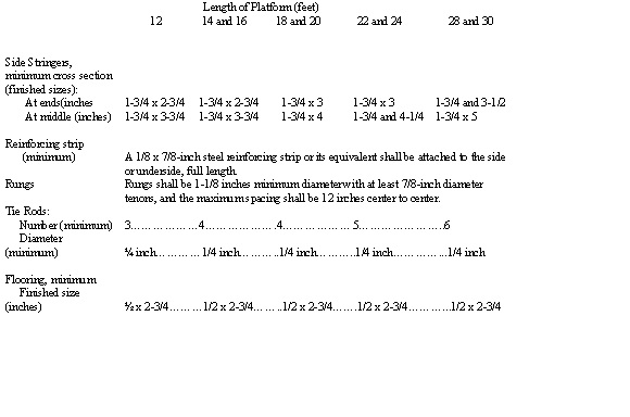
Table 10-11. Schedule for ladder-type platforms.
(L) Single-point adjustable suspension scaffolds.
(1) The scaffolding, including power units or manually operated winches, shall be of an approved type and meet the requirements of paragraph (C)(2) of this rule.
(2) All power-operated gears and brakes shall be enclosed.
(3) In addition to the normal operating brake, all power-driven units shall have an emergency brake which engages automatically when the normal speed of descent is exceeded.
(4) The units may be combined to form a two-point suspension scaffold. Such scaffold shall then comply with paragraph (K) of this rule.
(5) The supporting cable shall be vertical for its entire length.
(6) Suspension methods shall conform to applicable provisions of paragraphs (J) and (K) of this rule.
(7) The employee shall be protected by a safety harness and lifeline in accordance with paragraph (J) of rule 4123:1-3-03 of the Administrative Code. The attachment point of the lifeline to the structure shall be appropriately changed as the work progresses.
(M) Boatswains' chairs.
(1) When constructed of wood the chair seat shall be no less than twelve inches by twenty-four inches by one-inch thickness, reinforced by cleats on the underside to prevent splitting. A chair of the same size may be constructed of material of equal strength.
(2) Seat slings shall be of no less than five-eighths-inch diameter, "First Grade" manila rope, or its equivalent, which shall be reeved through the four seat holes so as to cross each other on the underside of the seat.
(3) Seat slings shall be of no less than three-eighths-inch wire rope when an employee is conducting a heat-producing process, such as gas or arc welding.
(4) The employee shall be protected by a safety belt or harness and lifeline in accordance with paragraph (J) of rule 4123:1-3-03 of the Administrative Code. The attachment point of the lifeline to the structure shall be appropriately changed as the work progresses.
(5) The tackle shall consist of correct size ball bearing or bushed blocks and properly spliced five-eighths-inch diameter, "First Grade" manila rope, or equivalent.
(6) The roofirons, hooks, or the object to which the tackle is anchored, shall be securely installed. Tiebacks shall be installed at right angles to the face of the building and securely fastened when using wall hooks.
(N) Carpenters' bracket scaffolds.
(1) The brackets shall consist of a triangular wood frame no less than two inches by three inches in cross section, or of metal of equivalent strength. Each member shall be properly fitted and securely joined.
(2) Each bracket shall be secured to the structure by a means which shall provide a factor of safety of no less than four.
(3) The brackets shall be spaced no more than eight feet apart.
(4) The platform shall consist of no less than two two-inch by ten-inch "Scaffold Grade" planks extending no more than twelve inches or less than six inches beyond each and support.
(O) Bricklayers' square scaffolds.
(1) Bricklayers' square scaffolds shall conform to "Table 10-12" and the square shall not exceed five feet in width and five feet in height.
(2) The squares shall be reinforced on both sides of each corner with one-inch by six-inch gusset pieces. They shall also have diagonal braces one inch by eight inches on both sides running from center to center of each member, or other means to secure equivalent strength and rigidity.
(3) The squares shall be set no more than five feet apart for medium duty scaffolds, and no more than eight feet apart for light duty scaffolds. Bracing, one inch by eight inches, extending from the bottom of each square to the top of the next square, shall be provided on both front and rear sides of the scaffold.
(4) Platform planks shall be no less than two-inch by ten-inch "Scaffold Grade." The ends of the planks shall overlap the bearers of the squares and each plank shall be supported by no less than three squares.
(5) Bricklayers' square scaffold shall not exceed three tiers in height and shall be so constructed and arranged that one square shall rest directly above the other. The upper tiers shall stand on a continuous row of planks laid across the next lower tier and be nailed down or otherwise secured to prevent displacement.
(6) Scaffolds shall be level and plumb and set upon a firm foundation.
Table 10-12. Minimum dimensions for bricklayers' square scaffold members.
| Members | Dimensions |
| Bearers or horizontal members | 2 x 6 in. |
| Legs | 2 x 6in. |
| Braces at corners | 1 x 6 in. |
| Braces diagonally from centerframe | 1 x 8in. |
(P) Foot scaffolds.
(1) Foot scaffolds shall not exceed eighteen inches in height, measured from the level upon which the supports are placed.
(2) Foot scaffolds imposed on other scaffolds when supported on brick or tile, shall be limited to eighteen inches in height and have a bearing surface of no less than ninety-six square inches. Supports shall be no more than seven feet cent to center.
(Q) Horse scaffolds.
(1) Horse scaffolds shall not be constructed or arranged more than two tiers in height.
(2) The members of the horses shall be no less than those specified in "Table 10-13."
(3) Horses shall be spaced no more than five feet for medium duty and no more than eight feet for light duty.
(4) When arranged in tiers, each horse shall be placed directly over the horse in the tier below.
(5) On all scaffolds arranged in tiers, the legs shall be nailed down or otherwise secured to the planks to prevent displacement or thrust and each tier shall be substantially cross braced.
(6) Defective or damaged horses or parts shall not be used.
Table 10-13. Minimum dimensions for horse scaffold members.
| Members | Dimensions |
| Horizontal members orbearers | 3 x 4in. |
| Legs | 1-1/4 x 4-1/2 in. |
| Longitudinal brace betweenlegs | 1 x 6in. |
| Gusset brace at top of legs | 1 x 8 in. |
| Half diagonalbraces | 1-1/4 x4-1/2 in. |
(R) Chimney, stack, or tank bracket scaffolds.
(1) Minimum width.
The minimum width of platform shall be no less than eighteen inches.
(2) Spacer blocks.
Spacer blocks, large enough to hold the suspending cable away form the structure, shall be provided.
(3) Ascending and descending.
For ascending to and descending from a chimney, stack or tank bracket scaffold, a scaling ladder or boatswain's chair shall be provided.
(4) Platforms on masonry chimneys or stacks.
Platforms supported on the rim of masonry chimneys or stacks are prohibited.
(5) Inside scaffolds.
In construction of chimneys or stacks where an inside scaffold is being used, the working platform shall be no less than eighteen inches below the top of the wall.
(6) Guardrails.
Chimney, stack, or tank bracket scaffolds shall be provided with standard guardrails, but no guardrail is required when safety belts or harness with lifelines are provided.
(S) Needle beam scaffolds.
(1) Wood needle beams shall be no less than four inches by six inches in size, with the greater dimensions placed in a vertical direction. Metal beams or the equivalent, conforming to paragraph (C)(2) of this rule may be used and shall not be altered or moved horizontally while they are in use.
(2) Ropes or hangers shall be provided for supports. The span between supports on the needle beam shall not exceed ten feet for four-inch by six-inch timbers. Rope supports shall be equivalent in strength to one-inch diameter "First Grade" manila rope.
(3) The scaffold shall be rigged so as to prevent the needle beam from rolling or becoming otherwise displaced.
(4) The platform span between the need beams shall not exceed eight feet when using two-inch "Scaffold Grade" planks. For spans greater than eight feet, platforms shall be constructed based on design requirements for the special span. The overhang of each end of the platform planks shall be no less than six inches and no more than twelve inches. Planks shall be secured against displacement.
(5) All unattached tools, bolts, and nuts used on needle beam scaffolds shall be kept in suitable containers, properly secured.
(6) One end of a needle beam scaffold may be supported by a permanent structural member conforming to paragraph (C)(2) of this rule.
(7) Each employee working on a needle beam scaffold shall be protected by a safety harness and lifeline in accordance with paragraph (J) of rule 4123:1-3-03 of the Administrative Code.
(T) Interior hung scaffolds.
(1) An interior hung scaffold shall be hung or suspended from a structure capable of providing a factor of safety of no less than four.
(2) The suspending wire or fiber rope shall be capable of supporting no less than six times the maximum rated load.
(3) The scaffold shall be designed to sustain a working load with a factor of safety of no less than four.
(4) For wood scaffolds, the following minimum "Scaffold Grade" material shall be used:
(a) Supporting bearers, two inches by ten inches on edge;
(b) Planking, two inches by ten inches, with maximum span of seven feet for heavy duty and ten feet for light duty or medium duty.
(5) Steel tube and coupler members may be used for such type scaffolds.
(U) Ladder jack scaffolds.
(1) All ladder jack scaffolds shall be limited to light duty and shall not exceed a height of twenty feet above the floor or ground.
(2) All ladders used in connection with ladder jack scaffolds shall be heavy duty ladders. Cleated ladder shall not be used for this purpose.
(3) The ladder jack shall be so designed and constructed that it will bear on the side rails in addition to the ladder rungs, or if bearing on rungs only, the bearing area shall be no less than ten inches on each rung.
(4) Ladder used in conjunction with ladder jacks shall be so placed, fastened, held, or equipped with devices so as to prevent slipping.
(5) The platform shall be "Scaffold Grade," two-inch by ten-inch plank, or material of equal strength. Planks shall overlap the bearing surface no less than twelve inches. The span between supports shall not exceed eight feet. Platform width shall be no less than eighteen inches and provide a factor of safety of no less than four.
(V) Window jack scaffolds.
(1) Window jack scaffolds shall be used only for the purpose of working at the window opening through which the jack is placed.
(2) Window jacks shall not be used to support planks spaced between one window jack and another or for other elements of scaffolding.
(3) Window jack scaffolds shall be provided with standard guardrails unless safety belts or harnesses with lifelines are attached and provided for the employee.
(4) No more than one employee shall be required to occupy a window jack scaffold.
(W) Float or ship scaffolds.
See appendix to this rule for examples of float or ship scaffolds.
(1) No more than three employees shall be required to occupy a float or ship scaffold.
(2) The platform shall be no less than three feet wide and six feet long, made of three-quarter-inch plywood, equal to "American Plywood Association Grade B-B, Group I, Exterior," or other equivalent material.
(3) Under the platform, there shall be two supporting bearers made from two-inch by four-inch, or one-inch by ten-inch, rough, select lumber or better. Bearers shall be free of knots or other flaws and project six inches beyond the platform on both sides. The ends of the platform shall extend six inches beyond the outer edges of the bearers. Each bearer shall be securely fastened to the platform.
(4) An edging of wood no less than three-fourths by one and one-half inches shall be placed around all sides of the platform to prevent tools from rolling off.
(5) Supporting ropes shall be one-inch diameter manila rope, or equivalent, providing a factor of safety of no less than six. Rope connections shall be such that the platform cannot shift or slip. Two ropes shall be used with each float, arranged so as to provide four ends which are to be securely fastened to an overhead support. Each of the two supporting ropes shall be securely fastened around one end of the bearer and pass under the platform to the other end of the bearer where it shall be securely fastened again, leaving sufficient rope at each end for the supporting ties.
(X) Form scaffolds.
See appendix to this rule for examples of various types of form scaffolds covered under this rule.
(1) General requirements for all form scaffolds.
(a) All form scaffolds and their components shall be capable of supporting without failure no less than four times the maximum rated load.
(b) Maximum permissible spans shall not exceed eight feet on centers for two-inch by ten-inch "Scaffold Grade" planking. Scaffold planks shall be securely fastened to the ledgers or of such length that they overlap the ledgers no less than six inches. Unsupported projecting ends of scaffolding planks of all form scaffolds shall be limited to a maximum overhang of twelve inches.
(2) Figure-four form scaffolds.
Figure-four form scaffolds are intended for light duty and shall not be used to support loads exceeding twenty-five pounds per square foot unless specifically designed for heavier loading. Frames shall be spaced no more than eight feet on centers. (For minimum design criteria, see "Table 10-14").
Table 10-14. Minimum design criteria for figure-four form scaffolds.
| Members | Dimensions |
| Uprights | 2 x 4 in. or 2 x 6 in. |
| Outrigger ledgers(two) | 1 x 6in. |
| Braces | 1 x 6 in. |
| Guardrails | 2 x 4 in. |
| Guardrail height | Approximately 42in. |
| Intermediate guardrails | 1 x 6 in. |
| Toeboards | 4 in. (minimum) |
| Maximum length ofledgers | 3 ft.6 in. (unsupported) |
| Planking | 2 x 10 in. |
| Uprightspacing | 8 ft.0 in. (on centers) |
(3) Metal bracket form scaffolds.
(a) Metal brackets or scaffold jacks which are an integral part of the form shall be securely bolted or welded to the form. Folding type brackets shall be either bolted or secured with a locking type pin when extended for use.
(b) "Clip-on" or "hook-over" brackets may be used, provided the form walers are bolted to the form or secured by snap ties or shea-bolt extending through the form and securely anchored.
(c) Metal brackets shall be spaced no more than eight feet on centers.
(d) Scaffold planks shall be either bolted to the metal brackets or of such length that they overlap the brackets at each end by no less than six inches. Unsupported projecting ends of scaffolding planks shall be limited to a maximum overhang of twelve inches.
(e) Metal bracket form scaffolds shall be equipped with standard guardrails and toeboards, meeting the minimum dimensions shown in "Table 10-15."
Table 10-15. Minimum design criteria for metal bracket form scaffolds.
| Members | Dimensions |
| Uprights | 2 x 4 in. |
| Guardrails | 2 x 4 in. |
| Guardrailheight | Approximately 42 in. |
| Intermediate guardrails | 1 x 6in. |
| Toeboards | 4 in. (minimum) |
| Planking | 2 x 9 in. |
(4) Wooden bracket form scaffolds.
Wooden bracket form scaffolds shall be an integral part of the form panel. The minimum design criteria set forth herein and in "Table 10-16" cover scaffolding intended for light duty and shall not be used to support loads exceeding twenty-five pounds per square foot, unless specifically designed for heavier loading.
Table 10-16. Minimum design criteria for wooden bracket form scaffolds.
| Members | Dimensions |
| Uprights | 2 x 4 in. or2 x 6 in. |
| Supportledgers | 2 x 6in. |
| Maximum scaffoldwidth | 3 ft. 6in. |
| Braces | 1 x 6 in. |
| Guardrails | 2 x 4in. |
| Guardrailheight | Approximately 42in. |
| Intermediateguardrails | 1 x 6in. |
| Toeboards | 4 in.(minimum) |
| Uprightspacing | 8 ft. 0 in. (oncenters) |
(Y) Pump jack scaffolds.
(1) Pump jack scaffolds shall:
(a) Not carry a working load exceeding five hundred pounds; and
(b) Be capable of supporting no less than four times the maximum rated load.
(c) The manufactured components shall not be loaded in excess of the manufacturer's recommended limits.
(2) Each pump jack bracket shall have two gripping mechanisms to prevent any failure or slippage.
(3) The platform bracket shall be fully decked and the planking secured. Planking, or equivalent, shall conform with paragraph (C)(7) of this rule.
(4) Poles and bracing.
(a) When wood scaffold planks are used as platforms, poles for pump jacks shall be spaced no more than ten feet center to center. When fabricated platforms are used that fully comply with all other provisions of this section, pole spacing may exceed ten feet center to center.
(b) Poles shall not exceed thirty feet in height.
(c) Poles shall be secured to the work surface by rigid triangular bracing, or equivalent, at the bottom, top and other points as necessary, to provide a maximum vertical spacing of no more than ten feet between braces. Each brace shall be capable of supporting a minimum of two hundred twenty-five pounds tension and compression.
(d) For the pump jack bracket to pass bracing already installed, an extra brace shall be used approximately four feet above the one to be passed until the original brace is reinstalled.
(e) All poles shall bear on mud sills or other firm foundations.
(f) Pole lumber shall be two-by-fours, of Douglas fir, or equivalent, straight-grained, clear, free of cross-grain, shakes, large knots, and other defects which might impair strength.
(g) When poles are constructed of two continuous lengths, they shall be two-by-fours, spiked together with the seam parallel to the bracket, and with ten-penny common nails, no more than twelve inches center to center, staggered uniformly from opposite outside edges.
(h) If two-by-fours are spliced to make up the pole, the splices shall be so constructed as to develop the full strength of the member.
(5) A ladder shall be provided for access to the platform during use.
(6) No more than two employees shall be required at any time to be on a pump jack scaffold between any two supports.
(7) Pump jack scaffolds shall be provided with standard guardrails, but no guardrail is required when safety harnesses with lifelines are provided for employees.
(8) When a work bench is used at an approximate height of forty-two inches, the top guardrail may be omitted in the space occupied by the work bench, if the work bench is fully decked, the decking is secure, and is capable of withstanding two hundred pounds pressure in any direction.
(9) Employees shall not be required to use a work bench as a scaffold platform.
(Z) Stilts.
Stilts shall be equipped with "feet" of skid resistant material. Means shall be provided to securely fasten the stilts to employee's feet and legs. The floor in the work area shall be maintained free of debris and other possible hazards.
Last updated June 9, 2021 at 8:14 AM
Supplemental Information