Rule 4123:1-5-10 | Mechanical power presses.


(A) Scope.
The specifications of this rule pertain to mechanical power presses. Excluded from the specifications of this rule are press brakes (when used for bending, see paragraph (F) of this rule), hydraulic and pneumatic power presses, bulldozers, hot bending and hot metal presses, forging presses and hammers, riveting machines and similar types of fastener applicators. For guarding of these excluded machines, see rule 4123:1-5-11 of the Administrative Code.
(B) Reserved.
(C) Mechanical power press guarding.
(1) Brakes.
Friction brakes provided for stopping or holding the slide movement will be inherently self-engaging by requiring power or force from an external source to cause disengagement. Brake capacity will be sufficient to stop the motion of the slide quickly and capable of holding the slide and its attachments at any point in its travel.
(2) Machines using full revolution clutches.
(a) Single-stroke mechanism.
Machines using full revolution clutches will incorporate a single-stroke mechanism.
(b) Compression-type springs.
If the single-stroke mechanism is dependent upon spring action, the spring(s) will be of the compression type, operating on a rod or guided within a bore or tube and designed to prevent interleaving of the spring coils in event of breakage.
(c) Two-hand trip.
A two-hand trip will have the individual operator's hand controls protected against unintentional operation and have the individual operator's hand controls arranged by design and construction and/or separation to require the use of both hands to trip the press and use a control arrangement requiring concurrent operation of the individual operator's hand controls.
(d) Anti-repeat feature.
Two-hand trip systems on full revolution clutch machines will incorporate an anti-repeat feature.
(e) Multiple-station presses.
Where two-hand trip systems are used on multiple-station presses, there will be a separate set of controls for each assigned employee.
(3) Foot pedals (treadle).
(a) Pedal mechanism.
The pedal mechanism will be protected to prevent unintended operation from falling or moving objects or by accidental stepping onto the pedal.
(b) Pedal return springs.
If pedal return springs are provided they will be of the compression type, operating on a rod or guided within a bore or tube, and designed to prevent interleaving of spring coils in event of breakage.
(c) Pedal counterweights.
If pedal counterweights are provided, the path of the travel of the weight will be enclosed.
(4) Hand-operated levers.
(a) Spring latch.
Hand-lever-operated power presses will be equipped with a spring latch on the operating lever to prevent premature or accidental tripping.
(b) More than one operating station.
The operating levers on hand-tripped presses having more than one operating station will be interlocked to prevent the tripping of the press except by the concurrent use of all levers.
(5) Machines using part revolution clutches.
(a) Clutch/brake control.
The clutch will release and the brake will be applied when the external clutch engaging means is removed, deactivated or deenergized.
(b) Stop control.
A red color stop control will be provided with the clutch/brake control system. Momentary operation of the stop control will immediately deactivate the clutch and apply the brake. The stop control will override any other control, and reactuation of the clutch will require use of the operating (tripping) means which has been selected.
(c) Control selection.
A means of selecting "off," "inch," "single stroke," and "continuous" (when the "continuous" function is furnished) will be supplied with the clutch/brake control to select type of operation of the press.
(d) Inch operating means.
An inch operating means will be provided and will prevent exposure of the employee's hands within the point of operation by:
(i) Requiring the concurrent use of both hands to actuate the clutch, or
(ii) Being a single control protected against accidental actuation and so located that the employee cannot reach into the point of operation while operating the single control.
(e) Two-hand controls for single stroke.
Two-hand controls for single stroke will conform to the following specifications:
(i) All controls will be protected against unintended operation.
(ii) The two-hand control system will permit an adjustment which will require concurrent pressure from both hands during the die closing portion of the stroke.
(iii) The two-hand control system will incorporate an anti-repeat feature.
(iv) The control system will require the operator to release all hand controls before an interrupted stroke can be resumed.
(v) Where two-hand trip controls are used on multiple-station presses, there will be a separate set of controls for each designated employee. Controls will be activated and deactivated in sets of two. The clutch/brake control system will prevent actuation of the clutch if all operating stations are bypassed.
(vi) The starting of a continuous run will require a separate action by the operator in addition to the setting for continuous stroking of the press before actuation of the operating controls will result in continuous stroking.
(vii) If foot control is provided, the selection method between foot or hand control will be separate from the stroking selector and will be designed so that the selection may be supervised by the employer.
(viii) Foot-operated controls will be guarded to prevent accidental operation.
(ix) Clutch/brake control systems will automatically deactivate in the event of failure of power or pressure supply for clutch engaging or failure of air supply. Reactivation will require restoration of normal power or air and the use of the tripping mechanisms.
(x) Turnover bar operation will be performed only when the power source is deenergized.
(6) Electrical.
(a) Disconnect switch.
A main power disconnect switch capable of being locked only in the "off" position will be provided with every power press control system.
(b) Motor start button.
The motor start button will be protected against accidental operation.
(c) Drive motor starter.
All mechanical power press controls will incorporate a type of drive motor starter that will disconnect the drive motor from the power source in the event of control voltage or power source failure, and require operation of the motor start button to restart the motor when voltage conditions are restored to normal.
(d) Accidental ground.
All clutch/brake control electrical circuits will be protected against the possibility of an accidental ground in the control circuit causing false operation of the press.
(7) Slide counterbalance systems.
(a) Spring counterbalance systems.
Spring counterbalance systems when used will:
(i) Incorporate means to retain system parts in event of breakage, and
(ii) Have the capability to hold the slide and its attachments at midstroke, without brake applied.
(b) Air counterbalance cylinders.
Air counterbalance cylinders will:
(i) Incorporate means to retain the piston and rod in case of breakage or loosening;
(ii) Have adequate capability to hold the slide and its attachments at any point in stroke, without brake applied; and
(iii) Incorporate means to prevent failure of capability (sudden loss of pressure) in event of air supply failure.
(8) Air controlling equipment.
Air controlling equipment will be protected against foreign material and water entering the pneumatic system of the press. A means of air lubrication will be provided when needed.
(9) Hydraulic equipment.
The maximum anticipated working pressures in any hydraulic system on a mechanical power press cannot exceed the safe working pressure rating of any component used in that system.
(10) Pressure vessels.
All pressure vessels used in conjunction with power presses will conform to the most current edition of "American Society of Mechanical Engineers Code for Pressure Vessels."
(11) Control reliability.
When specified by paragraph (D)(5) of this rule, the control system will operate so that a failure within the system does not prevent the normal stopping action from being applied to the press when specified, but will prevent initiation of a successive stroke until the failure is corrected. The failure will be detectable by a simple test, or indicated by the control system. This specification does not apply to those elements of the control system which have no effect on the protection against point of operation injuries.
(12) Brake system monitoring.
When specified by paragraph (D)(5) of this rule, the brake monitor will:
(a) Automatically prevent the activation of a successive stroke if the stopping time or braking distance deteriorates to a point where the safety distance being utilized does not meet the specifications set forth in paragraphs (D)(3)(c)(v) and (D)(3)(g)(iii) of this rule.
The brake monitor used with the type B gate or movable barrier device will be installed in a manner to detect slide top-stop overrun beyond the limit established by the employer.
(b) Indicate when the performance of the braking system has deteriorated to the extent described in paragraph (C)(12)(a) of this rule; and
(c) Monitor the brake system performance on each stroke.
(D) Safeguarding the point of operation.
(1) General specifications.
(a) It is the responsibility of the employer to provide and require the usage of "point of operation guards" or properly applied and adjusted "point of operation devices" on every operation performed on a mechanical press. (See Table 10-1 to this rule.)
(b) The specification of paragraph (D)(1)(a) of this rule does not apply when the point of operation opening is one-fourth inch or less. (See Table 10-1 to this rule.)
(2) Point of operation guards.
(a) Every point of operation guard will meet the following specifications:
(i) It will prevent entry of hands or fingers into the point of operation by reaching through, over, under, or around the guard;
(ii) It will conform to the maximum permissible openings of Table 10-1 to this rule;
(iii) It will , in itself, create no pinch point between the guard and moving machine parts;
(iv) It will utilize fasteners not readily removable by the operator, so as to minimize the possibility of misuse or removal of essential parts;
(v) It will be easy to inspect; and
(vi) It will offer maximum visibility of the point of operation consistent with the other specifications.
(b) When used, a die enclosure guard will be attached to the die shoe or stripper or both in a fixed position.
(c) When used, a fixed barrier guard will be attached securely to the frame of the press or to the bolster plate.
(d) Interlocked press barrier guard.
(i) When used, an interlocked press barrier guard will be attached to the press frame or bolster plate and will be interlocked with the press clutch control so that the clutch cannot be activated during normal production unless the guard itself, or the hinged or movable sections of the guard are in position to conform to the specifications of Table 10-1 to this rule.
(ii) The hinged or movable sections of an interlocked press barrier guard cannot be used to actuate the press during manual feeding. The guard will prevent opening of the interlocked section and reaching into the point of operation prior to the die closure or prior to the cessation of slide motion. See paragraph (D)(3)(b) of this rule regarding manual feeding through interlocked press barrier devices.
(e) When used, the adjustable barrier guard will be securely attached to the press bed, bolster plate, or die shoe, and will be adjusted and operated in conformity with Table 10-1 to this rule and the specifications of this paragraph.
(f) A point of operation enclosure which does not meet the specifications of paragraphs (D)(2)(a) to (D)(2)(e) of this rule and Table 10-1 to this rule will be used only in conjunction with point of operation devices.
(3) Point of operation devices.
(a) Point of operation devices will protect the operator by:
(i) Preventing and/or stopping normal stroking of the press if the operator's hands are inadvertently placed in the point of operation; or
(ii) Preventing the operator from inadvertently reaching into the point of operation or withdrawing his hands if they are inadvertently located in the point of operation, as the dies close; or
(iii) Preventing the operator from inadvertently reaching into the point of operation at all times; or
(iv) Requiring application of both of the operator's hands to machine operating controls and locating such controls at such a safety distance from the point of operation that the slide completes the downward travel or stops before the operator can reach into the point of operation with his hands; or
(v) Enclosing the point of operation before a press stroke can be initiated and maintaining this closed condition until the motion of the slide has ceased; or
(vi) Enclosing the point of operation before a press stroke can be initiated, so as to prevent an operator from reaching into the point of operation prior to die closure or prior to cessation of slide motion during the downward stroke.
(b) A gate or movable barrier device will protect the operator as follows:
(i) A type A gate or movable barrier device will protect the operator in the manner specified in paragraph (D)(3)(a)(v) of this rule; and
(ii) A type B gate or movable barrier device will protect the operator in the manner specified in paragraph (D)(3)(a)(vi) of this rule.
(c) A presence sensing point of operation device will protect the operator as provided in paragraph (D)(3)(a)(i) of this rule, and will be interlocked into the control circuit to prevent or stop slide motion if the operator's hand or other part of his body is within the sensing field of the device during the down-stroke of the press slide.
(i) The device will not be used on machines using full revolution clutches.
(ii) The device will not be used as a tripping means to initiate slide motion.
(iii) The device will be constructed so that a failure within the system does not prevent the normal stopping action from being applied to the press when specified , but does prevent the initiation of a successive stroke until the failure is corrected. The failure will be indicated by the system.
(iv) Muting (bypassing of the protective function) of such device, during the up-stroke of the press slide, is permitted for the purpose of parts ejection, circuit checking and feeding.
(v) The safety distance (Ds) from the sensing field to the point of operation will be greater than the distance determined by the following formula:
Ds = sixty-three inches/second x T s; where:
Ds = minimum safety distance (inches); sixty-three inches/second = hand speed constant; and
Ts = stopping time of the press measured at approximately ninety degree position of crankshaft rotation (seconds).
(vi) Guards will be used to protect all areas of entry to the point of operation not protected by the presence sensing device.
(d) The pull-out device will protect the operator as specified in paragraph (D)(3)(a)(ii) of this rule and will include attachments for each of the operator's hands.
(i) Attachments will be connected to and operated only by the press slide or upper die.
(ii) Attachments will be adjusted to prevent the operator from reaching into the point of operation or to withdraw the operator's hands from the point of operation before the dies close.
(iii) A separate pull-out device will be provided for each operator if more than one operator is used on a press.
(e) Sweep devices will not be used.
(f) A holdout or restraint device will protect the operator as specified in paragraph (D)(3)(a)(iii) of this rule and will include attachments for each of the operator's hands. Such attachments will be securely anchored and adjusted in such a way that the operator is restrained from reaching into the point of operation. A separate set of restraints will be provided for each operator if more than one operator is needed on a press.
(g) The two-hand control device will protect the operator as specified in paragraph (D)(3)(a)(iv) of this rule.
(i) When used in press operations needing more than one operator, separate two-hand controls will be provided for each operator and will be designed to require concurrent application of all controls to activate the slide. The removal of a hand from any control button will cause the slide to stop.
(ii) Each two-hand control will meet the construction specifications of paragraph (C)(5)(e) of this rule.
(iii) The safety distance (Ds) between each two-hand control device and the point of operation will be greater than the distance determined by the following formula:
Ds = sixty-three inches/second x Ts; where:
Ds = minimum safety distance (inches); sixty-three inches/second = hand speed constant; and
Ts = stopping time of the press measured at approximately ninety degree position of crankshaft rotation (seconds).
(h) The two-hand trip device will protect the operator as specified in paragraph (D)(3)(a)(iv) of this rule.
(i) When used in press operations needing more than one operator, separate two-hand trips will be provided for each operator, and will be designed to require concurrent application of all operators to activate the slide.
(ii) Each two-hand trip will meet the construction specifications of paragraph (C)(5)(e) of this rule.
(iii) The safety distance (Dm) between the two-hand trip and the point of operation will be greater than the distance determined by the following formula:
Dm = sixty-three inches/second x Tm; where:
Dm = minimum safety distance (inches); sixty-three inches/second = hand speed constant; and
Tm = the maximum time the press takes for the die closure after it has been tripped (seconds).
For full revolution clutch presses with only one engaging point, Tm is equal to the time necessary for one and one-half revolutions of the crank shaft. For full revolution clutch presses with more than one engaging point, Tm will be calculated as follows:
Tm = [1/2 + (one divided by number of engaging points per revolution)] x time necessary to complete one revolution of the crankshaft (seconds).
(4) Hand-feeding tools.
Hand-feeding tools are intended for placing and removing materials in and from the press. Hand-feeding tools are not a point of operation guard or protection device and will not be used in lieu of the guards or devices spedified in this paragraph.
(5) Additional specifications for safeguarding.
Where the operator feeds or removes parts by placing one or both hands in the point of operation, and a two-hand control, presence sensing device, type B gate, or movable barrier (on a part revolution clutch) is used for safeguarding:
(a) The employer will use a control system and a brake monitor which comply with paragraphs (C)(11) and (C)(12) of this rule;
(b) The control of air clutch machines will be designed to prevent a significant increase in the normal stopping time due to a failure within the opening valve mechanism, and to inhibit further operation if such failure does occur, where a part revolution clutch is employed.
(E) Design, construction, setting, and feeding of dies.
(1) General specifications.
The employer will furnish and require the use of hand tools for freeing and removing stuck work or scrap pieces from the dies, so that no employee need reach into the point of operation for such purposes.
(2) Scrap handling.
The employer will provide means for handling scrap from roll feed or random length stock operations. Scrap cutters used in conjunction with scrap handling systems will be safeguarded in accordance with paragraph (D) of this rule.
(3) Guide post hazard.
The hazard created by a guide post (when it is located in the immediate vicinity of the operator) when separated from its bushing by more than one-fourth inch will be considered as a point of operation hazard and be protected in accordance with paragraph (D) of this rule.
(4) Unitized tooling.
If unitized tooling is used, the opening between the top of the punch holder and the face of the slide, or striking pad, will be safeguarded in accordance with the specifications of paragraph (D) of this rule.
(5) Weight designation.
All dies will be stamped to indicate complete die weight when handling equipment may become overloaded.
(6) Die fastening.
Provision will be made in both the upper and lower shoes for securely mounting the die to the bolster plate and slide. Where clamp caps or setscrews are used in conjunction with punch stems, additional means of securing the upper shoe to the slide will be used.
(7) Die handling.
Handling equipment attach points will be provided on all dies needing mechanical handling.
(8) Diesetting.
(a) The employer will provide spring loaded turnover bars for presses designed to accept such turnover bars.
(b) The employer will provide die stops or other means to prevent losing control of the die while setting or removing dies in presses which are inclined.
(c) The employer will provide and require the use of safety blocks for use whenever dies are being adjusted or repaired in the press.
(d) The employer will provide and require the use of brushes, swabs, lubricating rolls, and automatic, or manual pressure guns to lubricate material, punches or dies.
(F) Power press brake (when used as a power press).
The specifications of this rule are applicable to power press brakes when used for other than bending operations.
(G) Hydraulic and pneumatic presses.
Hydraulic and pneumatic presses will be guarded in accordance with paragraph (E) of rule 4123:1-5-11 of the Administrative Code.
(H) Exceptions.
The specifications set forth in this rule do not apply to setting up or trying out dies.
Table 10-1
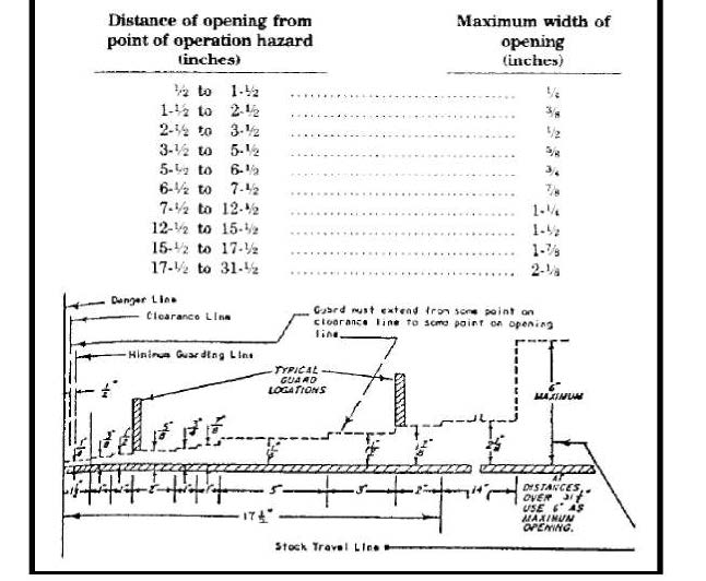
| Distance of opening from point of operation hazard (inches) | Maximum width of opening (inches) |
| 1/2 to 1-1/2 | 1/4 |
| 1-1/2 to 3-1/2 | 3/8 |
| 2-1/2 to 3-1/2 | 1/2 |
| 3-1/2 to 5-1/2 | 5/8 |
| 5-1/2 to 6-1/2 | 3/4 |
| 6-1/2 to 7-1/2 | 7/8 |
| 7-1/2 to 12-1/2 | 1-1/4 |
| 12-1/2 to 15-1/2 | 1-1/2 |
| 15-1/2 to 17-1/2 | 1-7/8 |
| 17-1/2 to 31-1/2 | 2-1/8 |
This diagram shows the accepted safe openings between the bottom edge of a guard and feed table at various distances from the danger line (point of operation)
The clearance line marks the distance needed to prevent contact between guard and moving parts.
The minimum guarding line is the distance between the infeed side of the guard and the danger line which is one-half inch from the danger line.
The various openings are such that for average size hands an operator's fingers will not reach the point of operation.
After installation of point of operation guards and before a job is released for operation a check should be made to verify that the guard will prevent the operator's hands from reaching the point of operation.
Last updated June 30, 2023 at 12:20 AM
Supplemental Information