Back To Top Top Back To Top
This website publishes administrative rules on their effective dates, as designated by the adopting state agencies, colleges, and universities.

Chapter 4123:1-5 | Workshops and Factories


Rule
Rule 4123:1-5-01 | Scope and definitions.
 

(A) Scope.

The purpose of this chapter of the Administrative Code is to provide reasonable safety for life, limb, and health of employees. In cases of practical difficulty or unnecessary hardship, the Ohio bureau of workers' compensation may grant exceptions from the literal requirements of the rules of this chapter to permit the use of other devices or methods when, in the opinion of the bureau, the equivalent protection is thereby secured.

The specific requirements of this chapter are requirements upon an employer for the protection of such employer's employees and no others and apply to all workshops and factories subject to the Workers' Compensation Act (sections 4123.01 to 4123.99 of the Revised Code). Specific requirements of other chapters of the Administrative Code adopted by the Ohio bureau of workers' compensation shall apply to the particular industry covered by any such other chapter, and, to the extent of conflict between this chapter and such other chapter, the latter shall govern, but in all other respects this chapter shall be deemed to apply and the other to be a supplement of this chapter.

Installations or constructions built or contracted for prior to the effective date (shown at the end of each rule) of any requirement shall be deemed to comply with the provisions of these requirements if such installations or constructions comply either with the provisions of these requirements or with the provisions of any applicable specific requirement which was in effect at the time contracted for or built.

(B) Definitions.

(1) "Access board (hot board)": a platform designed to be fastened to a pole or structure and having dielectric properties equal to dry wood.

(2) "Adjustable barrier guard": a barrier requiring adjustment for each job setup or die setup.

(3) "Aerial device": any vehicle-mounted telescoping or articulating device which is used to position personnel at job sites.

(4) "Air contaminants": concentrations of dust, mist, fume, gas or vapor, or any combination thereof when suspended in the atmosphere.

(5) "Air-lift hammer": (see "gravity hammers").

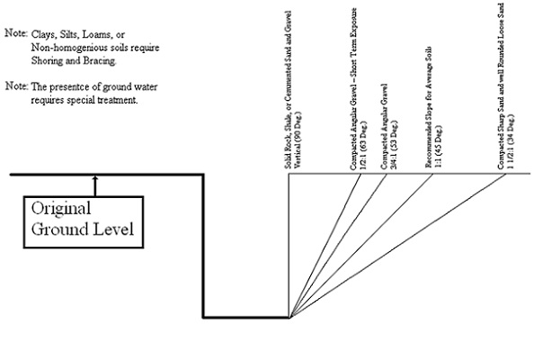
(6) "Angle of repose": the greatest angle above the horizontal plane at which unexcavated material will lie without sliding.

(7) "Anti-repeat": the part of the clutch/brake control system designed to limit a mechanical power press to a single stroke if the tripping means is held on the operating position. Anti-repeat requires release of all tripping mechanisms before another stroke can be initiated. Anti-repeat is also called "single stroke reset" or "reset circuit."

(8) "Approved": sanctioned, endorsed, accredited, certified, or accepted as satisfactory by a duly constituted and nationally recognized authority or agency.

(9) "Approved storage facility (magazine)": a facility for the storage of explosive materials covered by a license or permit issued under authority of the appropriate governmental agencies.

(10) "Bearer": a horizontal member of a scaffold upon which the platform rests and which may be supported by ledgers.

(11) "Blast area": the area in which explosives loading and blasting operations are being conducted.

(12) "Blaster": a person qualified to be in charge of and responsible for the loading and firing of a blast.

(13) "Blasting agent": any material or mixture consisting of a fuel and oxidizer intended for blasting, not otherwise classified as an explosive, and in which none of the ingredients are classified as an explosive, provided that the finished product, as mixed and packaged for use or shipment, cannot be detonated by means of a no. 8 test blasting cap when unconfined.

(14) "Blasting cap": (see "detonator").

(15) "Board-type drop hammer": (see "gravity hammers").

(16) "Boatswain's chair": a seat supported by slings attached to a suspended rope, designed to accommodate one employee in a sitting position.

(17) "Bolster plate": the plate attached to the top of the bed of a power press having drilled holes or T-slots for attaching the lower die or die shoe.

(18) "Brace":

(a) Scaffold

A tie that holds one scaffold member in a fixed position with respect to another member.

(b) Trench

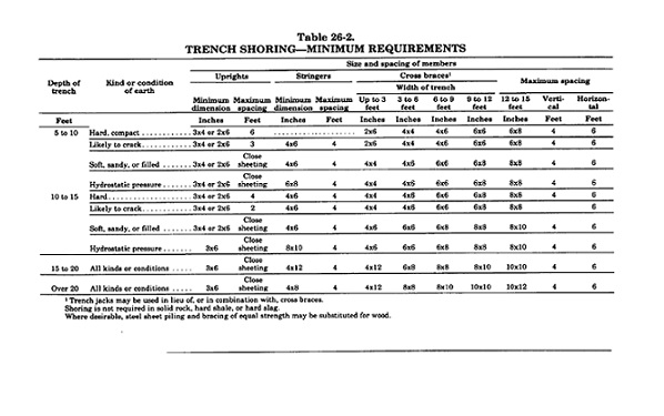
The horizontal members of the shoring system with ends bearing against the uprights or stringers.

(19) "Brake (mechanical power press)": the mechanism used to stop and hold the crankshaft, either directly or through a gear train, when the clutch is disengaged.

(20) "Brake monitor": a sensor designed, constructed, and arranged to monitor the effectiveness of a mechanical power press braking system.

(21) "Bulldozers": stationary power-driven machines used chiefly for bending operations. They have a movable head operated by links attached to the main drive gears and moving in a horizontal plane.

(22) "Circuit" a conductor or system of conductors through which an electric current flows or may flow.

(23) "Cleats": ladder crosspieces of rectangular cross-sections placed on edge on which an employee may step in ascending or descending.

(24) "Climbers": lineman's tools used on the legs and feet to enable the lineman to climb wooden poles.

(25) "Clutch": the coupling mechanism used on a mechanical power press to couple the flywheel to the crankshaft, either directly or through a gear train.

(26) "Collector" (see "separator").

(27) "Conductor": metallic material suitable for carrying an electric current.

(28) "Confined space": must meet all of the following three criteria:

(a) Is large enough and so configured that an employee can bodily enter and perform assigned work;

(b) Has limited or restricted means for entry or exit (for example, tanks, vessels, silos, storage bins, hoppers, vaults and pits are spaces that may have limited means of entry.); and

(c) Is not designed for continuous employee occupancy.

(29) "Contact distance (electrical)": that distance within which contact in doing the work or contact in the event of reaching, slipping, or falling may possibly occur.

(30) "Control system": sensors, manual input, and mode selection elements, interlocking and decision-making circuitry, and output elements to a mechanical power press operating mechanism.

(31) "Counterbalance": the mechanism that is used to balance or support the weight of the connecting rods, slide, and slide attachments on a power press.

(32) "Coupler": a device for locking together the component parts of a tubular metal scaffold.

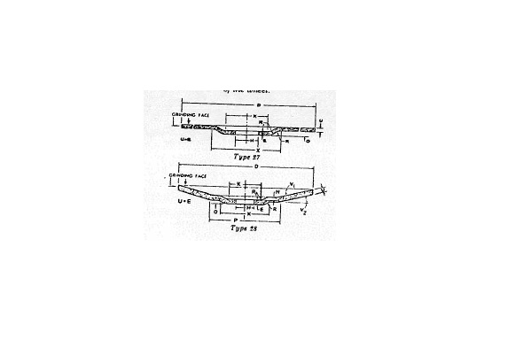
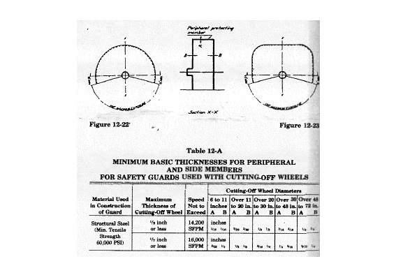
(33) "Cutting-off wheels": organically bonded wheels designed for use with power-driven equipment for a multitude of operations variously known as cutting, cutting-off, grooving, slotting, coping, jointing, etc.

(34) "Danger zone": the point of operation where a known hazard exists.

(35) "Deenergized": free from any electrical connection to a source of potential different from that of the earth.

(36) "Designated employee": an employee selected or assigned by the employer or the employer's representative as being qualified to perform specific duties.

(37) "Detonating cord": a flexible cord containing a center core of high explosives and used to initiate other explosives.

(38) "Detonator": any device containing a detonating charge that is used for initiating detonation in an explosive; the term includes, but is not limited to, electric blasting caps of instantaneous and delay types, blasting caps for use with safety fuse, detonating cord delay connectors, and non-electric instantaneous and delay blasting caps.

(39) "Dielectric": a nonconductor of electric current which will not absorb moisture, such as fiberglass, or equivalent.

(40) "Die setting": the process of placing or removing dies in or from a power press, and the process of adjusting the dies, other tooling, and safeguarding means to cause them to function properly and safely.

(41) "Die shoe": a plate or block upon which a die holder is mounted. A die shoe functions primarily as a base for the complete die assembly, and, when used, is bolted or clamped to the bolster plate or the face of the slide.

(42) "Dockboard (bridge plate)": a movable plate (usually metal) for bridging the gap between motor vehicle or freight car and a dock or loading platform.

(43) "Energized": anything connected to an electrical source having a greater potential than that of the earth.

(44) "Excavation": any man made cavity or depression in the earth's surface, including its sides, walls, or faces, formed by earth removal and producing unsupported earth conditions by reason of the excavation. If installed forms or similar structures reduce the depth-to-width relationship, an excavation may become a trench.

(45) "Exhaust system": includes suction systems, hoods, ducts, fans, separators, receptacles, and other parts necessary for the proper installation and operation thereof.

(46) "Explosive": any chemical compound or mixture that is intended for the purpose of producing an explosion.

(47) "Exposed to contact": the location of the material or object which, during the course of operation, is accessible to an employee in performance of the employee's regular or assigned duty.

(48) "Face of slide": the bottom surface of the slide to which the punch or upper die of a power press is generally attached.

(49) "Factor of safety": the ratio between the ultimate breaking stress and the working stress of the material, structure, or device. For example, the term "factor of safety of four" means that the material, structure, or device shall be constructed of such strength that the maximum load will be one-fourth the designed ultimate breaking load. Where other factors of safety appear, they shall apply in the same manner. The standard of "The American Society for Testing and Materials (ASTM)" shall be used in determining the strength of material except as otherwise provided herein.

(50) "Feed rolls": in-running rolls which perform no other function than to feed material to the point of operation.

(51) "Feeding": the process of placing or removing material within or from the point of operation. This may be done automatically, semi-automatically, or manually.

(52) "Fire-resistance rating": the measured time in hours or fractions thereof that the material or construction will withstand fire exposure, as determined by fire tests conducted in conformity with recognized standards.

(53) "Fire-resistive construction": a method of construction which prevents or retards the passage of hot gases or flames as defined by the fire-resistance rating.

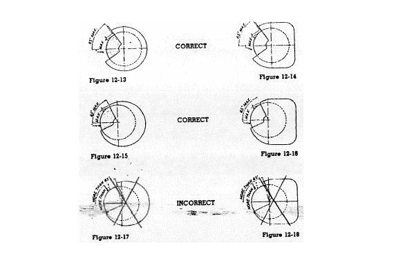
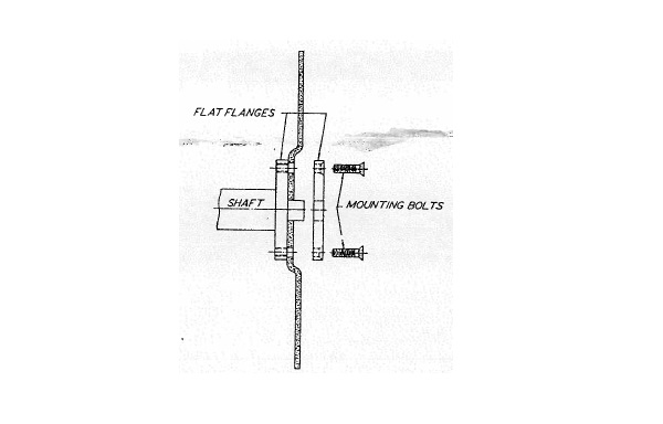
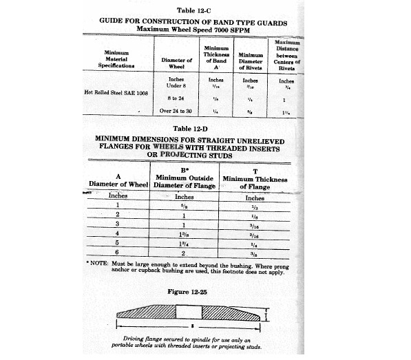
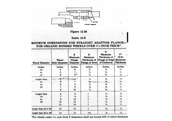
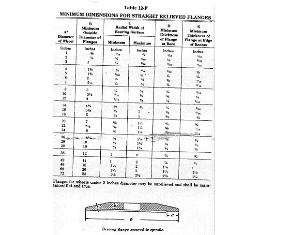
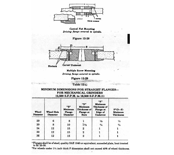
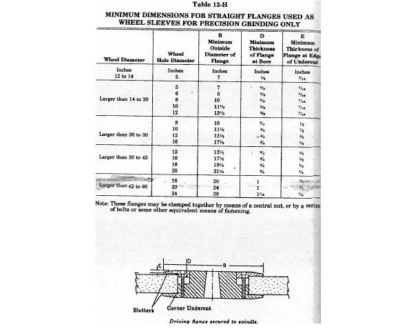
(54) "Flanges": collars, discs, or plates between which grinding wheels are mounted and are referred to as adaptor, sleeve, or back-up type.

(55) "Floor hole": A gap or open space in a floor, roof, horizontal walking-working surface, or similar surface that is two inches or more in its least dimension.

(56) "Floor opening": an opening measuring twelve inches or more in its least dimension, in any floor, platform, pavement, or yard, through which a person may fall; such as a hatchway, stair or ladder opening, pit or large manhole.

(57) "Foot control (part revolution clutch press)": the foot-operated control mechanism designed to be used with a clutch or clutch/brake control system.

(58) "Foot pedal (full revolution clutch press)": the foot-operated lever designed to operate the mechanical linkage that trips a full revolution clutch.

(59) "Forging": the product of work on metal formed to a desired shape by impact or pressure in hammers, forging machines (upsetters), presses, rolls, and related forming equipment.

(60) "Forging presses": a class of forging equipment wherein the shaping of metal between dies is performed by mechanical or hydraulic pressure.

(61) "Full revolution clutch (mechanical power press)": a type of clutch that, when tripped, cannot be disengaged until the crankshaft has completed a full revolution and the press slide a full stroke.

(62) "Fumes": small solid particles formed by the condensation of vapors of solid materials.

(63) "Gas": a formless fluid which tends to occupy an entire space uniformly at ordinary temperatures and pressures.

(64) "Gate" or "movable barrier device": a movable barrier arranged to enclose the point of operation before a power stroke can be started.

(65) "Grab bars": individual handholds placed adjacent to or as an extension above ladders for the purpose of providing access beyond the limits of the ladder.

(66) "Gravity hammers": A class of forging hammer wherein energy for forging is obtained by the mass and velocity of a freely falling ram and the attached upper die. Examples: board-type drop hammers and air-lift hammers.

(67) "Ground":

(a) "Ground connection": the equipment used in establishing a path between an electric circuit or equipment and earth. A ground connection consists of a ground conductor, a ground electrode, and the earth which surrounds the electrode.

(b) "Grounded": connected to earth by a ground connection.

(c) "Grounded effectively": connected to earth through a ground connection or connections of sufficiently low impedance and having sufficient current-carrying capacity to prevent the building up of voltages which may result in undue hazard to connected equipment or to employees.

(68) "Grounding conductor": a conductor which is used to connect the equipment or the wiring system with a grounding electrode or electrodes.

(69) "Guard": the covering, fencing, railing, or enclosure which shields an object from accidental contact. (See also "safety guard.")

(70) "Guarded": means that the object is covered, fenced, railed, enclosed, or otherwise shielded from accidental contact.

(71) "Guide post": the pin attached to the upper or lower die shoe, operating within the bushing on the opposing die shoe, to maintain the alignment of the upper and lower dies of a power press.

(72) "Handhold (handgrip)": a device attached to a manlift which can be grasped by the passenger to provide a means of maintaining balance.

(a) "Closed type": a cup-shaped device into which the passenger may place his fingers, open at the top in the direction of travel of the step for which it is to be used, and closed at the bottom.

(b) "Open type": one which has a handgrip surface fully exposed and capable of being encircled by the passenger's fingers.

(73) "Handrail": a a lengthwise member mounted directly on the wall, floor or partition by means of brackets that will furnish an adequate handhold for anyone grasping it to avoid falling.

(74) "Hazardous concentrations (as applied to air contaminants)": concentrations of air contaminants which are in excess of established occupational exposure limits.

(75) "Head protection devices":

(a) "Bump cap or hat": a thin-shelled plastic headgear worn to provide protection to the head from bumps or lacerations but does not meet the requirements for protective helmets.

(b) "Crown straps": that part of the suspension which passes over the head.

(c) "Hair enclosure": a hat or cap (other than a protective helmet or bump cap) or a hairnet specifically designed to protect the wearer from entanglement in moving parts of machines, equipment, or from exposure to sparks, hot metal, or ignition.

(d) "Protective helmet": a rigid headgear also known as a safety or hard hat, or as a safety or hard cap, that is worn to provide protection for the head, or portions thereof, against impact, flying articles, or electric shock, or any combination thereof, and which is held in place by a suitable suspension.

(e) "Suspension": the internal cradle of a protective helmet or bump cap which holds it in place on the head and is made up of the headband and crown straps.

(76) "Hood": that part of an exhaust system into which the contaminated air or dust, fumes, mist, vapor, or gas first enters.

(77) "Hot line (live line) tools": those tools which are especially designed for work on energized high voltage conductors and equipment.

(78) "Inch": an intermittent motion imparted to the slide (on mechanical power presses using part revolution clutches) by momentary operation of the inch operating means.

(79) "Kickouts": accidental release or failure of a shore or brace used in trenching.

(80) "Ladder":

(a) "Extension ladder": a portable ladder, adjustable in length. It consists of two or more sections traveling in guides or brackets so arranged as to permit length adjustment. Its size is designated by the sum length of the sections measured along the side rails.

(b) "Extension trestle ladder": a self-supporting portable ladder, adjustable in length, consisting of a trestle ladder base and a vertically adjustable single ladder, with an effective means for locking the ladders together. The size is designated by the length of the trestle ladder base.

(c) "Fixed ladder": a ladder permanently attached to a structure, building, or equipment.

(i) "Ladder cage": an enclosure which encircles the climbing space of the ladder and is securely fastened to the side rails of the ladder or to the structure.

(ii) "Ladder well": a permanent complete enclosure around a fixed ladder, which is securely fastened to the walls of the well.

(d) "Individual-rung ladder": a fixed ladder, each rung of which is individually attached to a structure, building, equipment, or manhole.

(e) "Platform stepladder": a modification of a portable stepladder with a working platform provided near the top.

(f) "Rail ladder": a fixed ladder consisting of side rails joined at regular intervals by rungs or cleats and fastened in full length or in sections to a building, structure, or equipment.

(g) "Sectional ladder": a portable ladder, nonadjustable in length, consisting of two or more sections so constructed that the sections may be combined to function as a single ladder. Its size is designated by the overall length of the assembled sections.

(h) "Side-rolling ladder": a semifixed ladder, nonadjustable in length, supported by attachments to a guide rail, which is generally fastened to shelving, the plane of the ladder being also its plane of motion.

(i) "Side-step ladder": one from which an employee getting off at the top must step sideways in order to reach the landing.

(j) "Single ladder": a portable, nonadjustable ladder consisting of only one section.

(k) "Stepladder": a self-supporting portable ladder, nonadjustable in length, having flat steps or treads and a hinged back. Its size is designated by the overall length of the ladder measured along the front edge of the side.

(l) "Through ladder": one from which an employee getting off at the top must step through the rails in order to reach the landing.

(m) "Trestle ladder": a self-supporting portable ladder, nonadjustable in length, consisting of two sections hinged at the top to form equal angles with the base. The size is designated by the length of the side rails measured along the front edge.

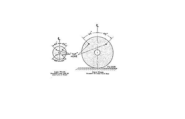
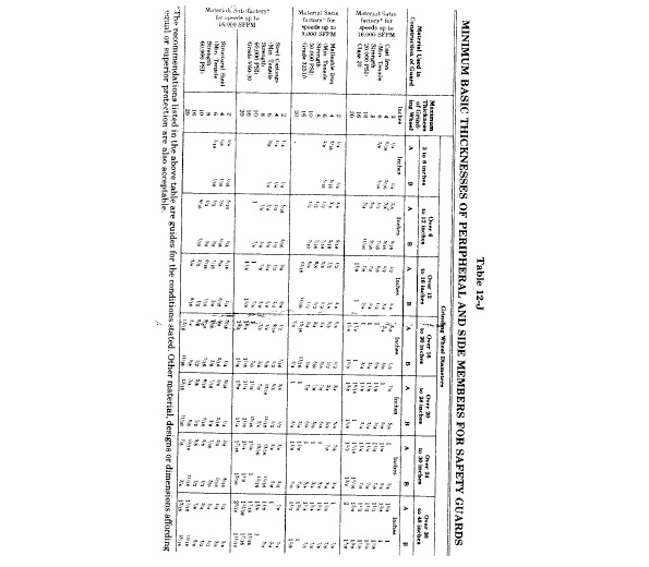
(81) "Lanyard": a flexible line of rope, wire rope, or strap, which generally has a connector at each end for connecting the body belt or body harness to a deceleration device, lifeline, or anchorage.

(82) "Leading wire": an insulated wire used between the electric power source and the electric blasting cap circuit.

(83) "Ledger (stringer)": a horizontal scaffold member which extends from post to post and which supports the putlogs or bearer forming a tie between the posts.

(84) "Lifeline": a component consisting of a flexible line for connection to an anchorage at one end to hang vertically (vertical lifeline), or for connection to anchorages at both ends to stretch horizontally (horizontal lifeline) and which serves as a means for connecting other components of a personal fall arrest system to the anchorage.

(85) "Limit switch": a device on a manlift for the purpose of cutting off the power to the motor and applying the brake to stop the carrier in the event that a loaded step passes the terminal landing.

(86) "Magazine": (see "approved storage facility").

(87) "Manlift": a device consisting of a power-driven endless belt with steps or platforms and handholds attached to it for the transportation of personnel from floor to floor.

(88) "Mist": small droplets of materials that are ordinarily liquid at normal temperature and pressure.

(89) "Nominal": in name or form, but not in fact; for example, a piece of lumber described as four inches by four inches but which, in fact, meets a standard which is less.

(90) "Non-current carrying": not intended to be energized.

(91) "Off-hand grinding": the grinding of any material or part which is held in the operator's hand.

(92) "Operator": any employee assigned or authorized to work at the specific equipment.

(93) "Part revolution clutch": a type of clutch that can be disengaged at any point before the crankshaft has completed a full revolution and the press slide a full stroke.

(94) "Pinch, nip, or shear point": the point or points at which it is possible to be caught between the moving parts of a machine, or between the moving and stationary parts of a machine, or between the material and the moving part or parts of a machine.

(95) "Pitch": the included angle between the horizontal and the ladder measured from the opposite side of the ladder from the climbing side.

(96) "Platform": a working space for employees elevated above the surrounding floor or ground.

(97) "Point of operation": the area where material is actually positioned and work is being performed during any process.

(98) "Polishing wheels": wheels designed for use with power-driven equipment to apply a luster or polish to materials.

(99) "Portable explosive-actuated fastening tool": a tool which depends upon an explosive charge to propel or discharge a stud, pin, or fastener, for the purpose of impinging it upon, affixing it to, or penetrating another object or material.

(a) "High-velocity tool": a tool or machine which, when used with a load, propels or discharges a stud, pin, or fastener at velocities in excess of three hundred feet per second.

(b) "Low-velocity tool": a tool or machine which, when used with a load, propels or discharges a stud, pin, or fastener at velocities not in excess of three hundred feet per second.

(100) "Power shears": power-driven machines used for cutting bars, slabs, sheets, or other material.

(101) "Presence sensing device": a device that creates a sensing field or area and deactivates the clutch control and activates the brake of a power press when any part of the operator's body or a hand tool is within such field or area.

(102) "Press": a powered machine that shears, punches, forms, or assembles metal or other material by means of cutting, shaping, or by combination dies attached to slides. A press consists of a stationary bed or anvil, and a slide (or slides) having a controlled reciprocating motion toward and away from the bed surface, the slide being guided in a definite path by the frame of the press.

(103) "Primed cartridge": a cartridge of explosives to which a detonator has been attached as a means of firing.

(104) "Protective shield or guard": a device, attached to the muzzle end of a portable explosive-actuated fastening tool, which is designed to confine flying particles.

(105) "Pull-out device": a mechanism attached to the operator's hands and connected to the upper die or slide of a power press, that is designed, when properly adjusted, to withdraw the operator's hands as the dies close when the operator's hands are inadvertently within the point of operation.

(106) "Railing": a vertical barrier erected above exposed edges of a floor opening, wall opening, ramp, platform, or runway to prevent falls of employees.

(107) "Rated load (roof car suspended platforms)": the combined weight of employees, tools, equipment, and other material which the working platform is designed to lift.

(108) "Rated speed": the speed for which a tool or piece of equipment is designed.

(109) "Repeat": an unintended or unexpected successive stroke of a power press resulting from a malfunction.

(110) "Respiratory devices":

(a) "Air-purifying respirator": a respirator with an air-purifying filter, cartridge, or canister that removes specific air contaminants by passing ambient air through the air-purifying element. These include:

(i) "Mechanical-filter respirator": a respirator which provides respiratory protection against particulate matter, such as nonvolatile dust, mists, or metal fumes.

(ii) "Chemical-cartridge respirator": a respirator equipped with a filter, sorbent, or catalyst, or combination of these items, which removes specific contaminants from the air passing through the air-purifying element.

(b) "Supplied-air respirator": an atmosphere-supplying respirator for which the source of breathing air is not designed to be carried by the user.

(c) "Self-contained breathing apparatus": an atmosphere-supplying respirator for which the source of breathing air is designed to be carried by the user.

(111) "Roof car": (see "scaffolds").

(112) "Roof car suspended platform": (see "scaffolds").

(113) "Roof-powered platform": (see "scaffolds").

(114) "Runway": a passageway for employees elevated above the surrounding floor or ground level.

(115) "Safety belt" or " body belt": a strap with means both for securing it around the waist and for attaching it to a lanyard, lifeline, or deceleration device.

(116) "Safety block": a prop that, when inserted between the upper and lower dies of a power press or between the bolster plate and the face of the slide, prevents the slide from falling of its own dead weight.

(117) "Safety guard (grinding wheel)": a device designed to restrain the pieces of a grinding wheel in the event the wheel is broken in operation.

(118) "Safety harness" or "body harness": a design of straps which may be secured about the employee in a manner that will distribute the fall arrest forces over at least the thighs, pelvis, waist, chest and shoulders with means for attaching it to other components of a personal fall arrest system.

(119) "Scaffold":

(a) " Mobile scaffold": a powered or unpowered, portable, caster or wheel-mounted supported scaffold.

(b) "Mobile work platform": generally a fixed work level, one frame high, on casters or wheels, with bracing diagonally from platform to vertical frame.

(c) "Roof car": a structure for the suspension of a working platform, providing for its horizontal movement to working positions.

(d) "Roof car suspended platform": equipment to provide access to the exterior of a building consisting of a suspended power-operated working platform, a roof car, and the operating and control devices.

(e) "Roof-powered platform": the working platform of a roof car suspended platform having the raising and lowering mechanism located on a roof car.

(f) "Self-powered platform": a working platform, of a roof car suspended platform, having the raising and lowering mechanism located on the working platform.

(g) "Swinging scaffold": a power- or manually operated platform suspended by two or more lines and independent of the building except for attachment at the roof or parapet.

(h) "Tube and coupler scaffold": an assembly consisting of tubing which serves as posts, bearers, braces, ties, and runners, a base supporting the posts, and special couplers which serve to connect the uprights and to join the various members.

(i) "Tubular welded frame scaffold": a sectional panel, or frame metal scaffold substantially built up of prefabricated welded sections which consist of posts and horizontal bearer with intermediate members. Panels or frames shall be braced with diagonal or cross braces.

(j) "Two-point suspension scaffolds": a scaffold suspended from overhead supports, the platform of which is supported by stirrups or hangers at two points to permit raising or lowering.

(120) "Securely fastened": the object or thing referred to shall be substantially fixed in place.

(121) "Self-powered platform": (see "scaffold").

(122) "Separator (collector)": that part of an exhaust system, the purpose of which is to separate material from the air which conveys it.

(123) "Shaft": an excavation made from the surface of the ground the longer axis of which forms an angle with the vertical of no more than forty-five degrees.

(124) "Shall": to be construed as mandatory.

(125) "Sheet pile": a pile, or sheeting, that may form one of a continuous interlocking line, or a row of timber, concrete, or steel piles, driven in close contact to provide a tight wall to resist the lateral pressure of water, adjacent earth, or other materials.

(126) "Sides," "walls," or "faces": the vertical or inclined earth surfaces formed as a result of trenching or excavation work.

(127) "Single-stroke mechanism (mechanical power press)": an arrangement used on a full revolution clutch to limit the travel of the slide to one complete stroke at each engagement of the clutch.

(128) "Slide": the main reciprocating member of a power press. A slide is also called a ram, plunger, or platen.

(129) "Sling": an assembly which connects the load to the material handling equipment.

(130) "Split-rail switch": an electric limit switch operated mechanically by the rollers of manlift steps. It consists of an additional hinged or "split" rail, mounted on the regular guide rail, over which the step rollers pass. It is springloaded in the "split" position. If the step supports no load, the rollers will "bump" over the switch; if a loaded step should pass over the section, the split rail will be forced straight, tripping the switch and opening the electrical circuit.

(131) "Standard guard railing": a substantial barrier, constructed in accordance with paragraph (E) of rule 4123:1-5-02 of the Administrative Code.

(a) "Top rail": the top lateral member of a standard guard railing.

(b) "Intermediate rail": the lateral member or members of a standard guard railing, installed at intervals of no more than twenty-one inches.

(132) "Steam hammers": a type of drop hammer where the ram is raised for each stroke by a double-action steam cylinder and the energy delivered to the workpiece is supplied by the velocity and weight of the ram and attached upper die driven downward by steam pressure. Energy delivered during each stroke may be varied.

(133) "Stop control": an operator control on a mechanical power press designed to immediately deactivate the clutch control and activate the brake to stop slide motion.

(134) "Stripper": a mechanism or die part on a power press for removing the parts or material from the punch.

(135) "Stud, pin, or fastener (as used in portable fastening tools)": a fastening device specifically designed and manufactured for use in portable explosive-actuated fastening tools.

(136) "Substantial (referring to material things)": constructed of such strength, or of such materials, and of such workmanship that the object will withstand the wear, usage, or shock for which it is designed.

(137) "Sweep device": a single or double arm (rod) attached to the upper die or slide of the press and designed to move the operator's hands to a safe position as the dies close, if the operator's hands are inadvertently within the point of operation. The sweep device may not be used for point of operation safeguarding.

(138) "Swinging scaffold": (see "scaffold").

(139) "Toeboard": a vertical barrier erected along exposed edges of a floor opening, platform, runway, ramp, or scaffold to prevent falls of material.

(140) "Travel" (manlifts): the distance between the centers of the top and bottom pulleys.

(141) "Traveling cable": a cable made up of electrical or communication conductors or both, and providing electrical connection between the working platform and the roof car or other fixed point.

(142) "Trench (when used as a noun)": a narrow excavation made below the surface of the ground. In general, the depth is greater than the width, but the width of a trench at the bottom is no greater than fifteen feet.

(143) "Trench boxes (safety cages, trench shields)": a shoring system composed of steel plates and bracing, welded or bolted together, which can be moved along as work progresses and protects employees from movement of earth and cave-ins.

(144) "Trench jack": a screw or hydraulic-type jack used as cross bracing in a trench shoring system.

(145) "Turnover bar": a bar used in die setting to turn manually the crankshaft of a mechanical power press.

(146) "Two-point suspension scaffold": (see "scaffold").

(147) "Unitized tooling": a type of die in which the upper and lower members are incorporated into a self-contained unit so arranged as to hold the die members in alignment.

(148) "Uprights": the vertical members of a shoring system.

(149) "Upsetting machines (forging machines, headers)": a type of forging equipment in which the main forming energy is applied horizontally to the workpiece which is gripped and held by prior action of the dies.

(150) "Ventilation":

(a) "Dilution ventilation": ventilation provided to reduce the concentration of air contaminants in the atmosphere of all or part of the place of employment.

(b) "General ventilation": ventilation of the general atmosphere in the place of employment.

(c) "Local exhaust ventilation": that type of ventilation in which suction is applied at the point of generation or escape of air contaminants.

(151) "Wales (stringers)": the horizontal members of a shoring system with sides bearing against the uprights or earth.

(152) "Wall and chute openings": openings in any wall or partition from which there is a drop of more than four feet and which are thirty inches or more in height and eighteen inches or more in width through which an individual may inadvertently fall. Windows shall not be considered wall openings except when located at the foot of any flight of stairs or at any platform on stairs. Where windows or openings are filled in with glass block, metal frame with sash bars, or wire mesh types, they shall not be considered wall openings.

(153) "Wall hole": an opening less than thirty inches but more than one inch high, of unrestricted width, in a wall or partition, such as a ventilation hole or drainage scupper.

Last updated May 15, 2023 at 12:24 PM

Supplemental Information

Authorized By: 4121.12, 4121.121, 4121.13
Amplifies: 4121.12, 4121.121, 4121.47
Five Year Review Date: 2/1/2027
Prior Effective Dates: 8/1/1977, 1/1/1986, 4/1/1999
Rule 4123:1-5-02 | Guarding floor and wall openings and holes.
 

(A) Scope.

This rule coves the guarding of floor and wall openings and holes. It shall not apply to industrial grating holes nor to the working face of floor openings which are occupied by elevators, dumbwaiters, conveyors, machinery, piping or containers; the loading and unloading areas of automotive truck and railroad docks, or platforms, scaffolds, pits and trenches which are occupied for the purpose of providing access to a product, facility or process equipment while being worked upon.

(B) Reserved.

(C) Permanent openings - floor, wall and yard.

(1) Floor openings.

(a) Guarding.

(i) Floor openings four feet or more above a lower level shall be guarded by one or more of the following: covers, standard guardrail systems, travel restraint systems, or personal fall arrest systems.

(ii) When an overhead obstruction prevents the use of standard railing, the top of the railing shall be constructed not more than ten inches below the overhead obstruction.

(iii) Removable or hinged railings or a substantial chain or wire rope section shall be installed when operations prevent installation of standard railing or fixed safety covers with flush hinges.

(b) Work below floor openings.

Where employees are required to work below a floor opening, toeboards shall be installed.

(c) Safety covers.

When a safety cover is used to protect an opening, the unused sides of the opening shall be guarded when the cover is raised.

(d) Guarding manholes, handholes, gratings and excavations.

Barriers, barricades or standard guard railings shall be provided for guarding open manholes, handholes, gratings or excavations and shall be visible at all times.

(2) Floor holes - guarding.

(a) Every floor hole into which employees can accidentally walk shall be guarded by one or more of the following:

(i) A standard guardrail system and toeboard on all exposed sides,

(ii) A fixed, hinged floor hole cover of substantial strength and construction. While the cover is not in place, the floor hole shall be attended by an employee designated by the employer or shall be guarded by a removable standard railing,

(iii) Travel restraint systems, or

(iv) Personal fall arrest systems.

(b) Every floor hole into which employees cannot accidentally walk (on account of fixed machinery, equipment, or walls) shall be protected by a cover that leaves no openings more than one inch wide. The cover shall be securely held in place to prevent tools or materials from falling through.

(3) Wall openings and holes, including chute openings.

(a) Wall opening - guarding.

(i) Wall openings shall be guarded by standard railings and toeboards, or with doors or gates or substantial screens which shall extend to a minimum height of forty-two inches, plus or minus three inches, measured from the floor or platform level.

(ii) When the top of the wall openings, protected by a railing, prevents installation of standard guard railing, the top rail shall be not be more than ten inches below the top of the wall opening.

(b) Wall hole - guarding.

Where there is a hazard of materials falling through a wall hole, and the lower edge of the near side of the hole is less than four inches above the floor, and the far side of the hole more than five feet above the next lower level, the hole shall be guarded by a toeboard, or an enclosing screen either of solid construction, or as specified in rule 4123:1-5-99 of the Administrative Code.

(c) Openings used for unloading materials - guarding.

(i) Openings used for unloading material into chutes, hoppers or bins when not in use, shall be guarded.

(ii) Area at discharge end of chutes:

The area at the discharge end of chutes shall be guarded if employees are required to work in, or pass through the area. If the chute discharges into a bin, conveyor, truck, railroad car, or other container, guarding shall not be required, but warning signs of conspicuous and easily read style shall be posted to warn employees when there is a hazard from falling, flying, moving or sliding objects.

(4) Working pits.

Working pits shall be guarded when not in use.

(5) Open vats, open soaking pits and open tanks.

(a) Sides of such vats, soaking pits, and tanks, containing injurious chemicals or other materials, shall extend to a height of not less than thirty-six inches above the working floor level or shall be guarded by standard guard railing. Employees shall not be required to work over such vats, soaking pits and tanks except on elevated runways, platforms and walkways (see paragraph (D)(1) of this rule).

(b) This shall not apply to open vats, soaking pits and open tanks designated as restricted areas where product is handled by conveyor or cab-controlled overhead crane.

(6) Galvanizing tanks.

Galvanizing tanks shall have a minimum height of thirty inches. At such height the wall thickness or bench shall be no less than thirty-two inches in width. For each increase in height of one inch the wall thickness or bench may be reduced by four inches.

(D) Elevated platforms, runways and walkways.

This rule does not apply to scaffolding.

(1) Guarding.

(a) Elevated platforms, runways and walkways four feet or more above floor or ground level shall be guarded with standard railings and toeboards. All elevated runways, platforms and walkways, regardless of height, located over or adjacent to water, machinery, open vats, open soaking pits or open tanks shall be provided with standard railing and toeboards.

(b) When the requirement prescribed above would result in an impairment of the work being performed, alternative protection may be provided for employees. Such alternative protection shall provide safety equivalent to or greater than that required in paragraph (D)(1)(a) of this rule.

(2) Support.

Elevated runways, platforms and walkways, made of planks shall be supported at least every five feet and the planks shall be securely fastened together with cleats underneath.

(3) Openings (drainage, ventilation, etc.).

Openings for drainage, ventilation, etc. in floors, elevated runways, platforms and walkways four feet or more above floor or ground level where employees are required to work below, shall not be greater than one inch in width.

(4) Special purpose runways.

Runways used exclusively for special purposes, such as oiling, shafting, or filling tank cars, may have the railing on one side omitted where operating conditions necessitate such omission, provided the falling hazard is minimized by using a runway of not less than eighteen inches wide.

(E) Standard guard railings, intermediate rail and toeboards.

A standard guard railing shall be constructed as a substantial barrier, securely fastened in place, and free from protruding objects, such as nails, screws and bolts, to protect openings or prevent accidental contact with some object, which barrier shall consist of a top rail not less than forty-two inches, plus or minus three inches above the working level, and unless the space between the top rail and the working level is covered with substantial material, an intermediate rail. Minimum material requirements shall be:

(1) Metal.

Top rail and intermediate railings shall be at least one and one half inch nominal diameter pipe, or two by two by three eighths inch angle structural steel, steel cable at least one-quarter inch in diameter or in thickness, or other metal shapes of equivalent bending strength with posts spaced not more than eight feet on centers.

(2) Wood.

For wood railings, the posts shall be of at least two inch by four inch stock spaced not to exceed six feet; the top and intermediate rails shall be of at least two inch by four inch stock. If top rail is made of two right-angle pieces of one inch by four inch stock, posts may be spaced on eight foot centers, with two inch by four inch intermediate rail.

(3) Toeboards.

A standard toeboard shall be four inches nominal in vertical height from its top edge to the level of the floor, platform, runway, or ramp. It shall be securely fastened in place and with not more than one fourth inch clearance above floor level. It may be made of any substantial material either solid or with openings not over one inch in greatest dimension.

Where material is piled to such height that a standard toeboard does not provide protection, paneling from floor to intermediate rail, or to top rail shall be provided.

(F) Stairway railings, guards and treads.

(1) Standard stair railings and standard handrails.

Every flight of stairs having four or more risers shall be equipped with standard stair railings or standard handrails as specified in the following, the width of the stair to be measured clear of all obstructions except handrails:

(a) On stairways less than forty-four inches wide having both sides enclosed, at least one handrail, preferably on the right side descending;

(b) On stairways less than forty-four inches wide having one side open, at least one stair railing on the open side;

(c) On stairways less than forty-four inches wide having both sides open, one stair railing on each side;

(d) On stairways more than forty-four inches but less than eighty-eight inches wide, one handrail on each enclosed side and one stair railing on each open side;

(e) On stairways eighty-eight or more inches wide, one handrail on each enclosed side, one stair railing on each open side, and one intermediate stair railing located approximately midway of the width.

(2) Winding stairs.

Winding stairs shall be equipped with a handrail offset to prevent walking on all portions of the treads having width less than six inches.

(3) Uniform treads.

All stairways shall have risers and treads of uniform dimensions in each run, except winding stairs as covered in paragraph (F)(2) of this rule.

(G) Dockboards (bridge plates).

(1) Portable and powered dockboards shall be substantial enough to carry the load imposed on them.

(2) Portable dockboards shall be secured in position, either being securely fastened or equipped with devices which will prevent slipping.

(3) Handholds, or other effective means shall be provided on portable dockboards.

(4) Positive protection shall be provided to prevent railroad cars or motor vehicles from moving or being moved while dockboards or bridge plates are in position.

(H) Stairways.

(1) "Stairway" means one or more flights of stairs and the necessary landings and platforms connecting them to form a continuous and uninterrupted passage from one floor or level to another.

(2) Flight of stairs.

(a) Four or more risers between landings shall be considered a flight of stairs.

(b) This does not apply to steps over a conveyor or to a working platform in connection with production lines or process units where access is for the performance of work, and the steps are not considered a passageway for general travel.

(I) Handrails.

Handrails shall be free of protruding nails or screws and not less than thirty inches and not more than thirty-eight inches in height, as measured from the leading edge of the stair tread to the top surface of the handrail.

Last updated May 12, 2023 at 2:50 PM

Supplemental Information

Authorized By: 4121.12, 4121.121, 4121.13
Amplifies: 4121.12, 4121.121, 4121.47
Five Year Review Date: 2/1/2027
Prior Effective Dates: 4/1/1964
Rule 4123:1-5-03 | Ladders and scaffolds.
 
This rule was filed with the Legislative Service Commission in PDF format and is presented here as filed.
View Rule Text

Last updated May 12, 2023 at 2:50 PM

Supplemental Information

Authorized By: 4121.12, 4121.121, 4121.13
Amplifies: 4121.47
Five Year Review Date: 2/1/2027
Prior Effective Dates: 4/1/1964, 8/1/1977
Rule 4123:1-5-04 | Mechanical power transmission apparatus.
 

(A) Scope.

This rule applies to mechanical power transmission apparatus and facilities to transmit power to operating equipment or machine tools. This rule shall not be construed as being applicable to power transmission facilities located within the frame or the equipment and exposure is necessary to its operation or adjustment.

(B) Reserved.

(C) Belts and pulleys.

This paragraph covers all types and shapes of power-transmission belts, except the following when operating at two hundred fifty feet per minute or less: flat belts one inch or less in width, flat belts two inches or less in width which are free from metal lacings or fasteners, round belts one-half inch or less in diameter; and single strand V-belts, the width of which is thirteen thirty-seconds inch or less.

(1) Horizontal belts (not including conveyors or conveyor belts).

Horizontal belts and pulleys seven feet or less above floor or platform shall be guarded as follows:

(a) Where both runs of horizontal belts are seven feet or less from floor level, the guard shall extend to at least fifteen inches above the belt or to a standard height, except that where both runs of a horizontal belt are forty-two inches or less from the floor, the belt shall be fully enclosed in accordance with rule 4123:1-5-99 of the Administrative Code. Note: In power or power development plants a standard guard railing may be used in lieu of this requirement.

(b) If lower part of belt is seven feet or less above platform or floor level and upper part of belt more than seven feet above platform or floor level, the lower part of belt and pulley shall be guarded on bottom, sides, and ends, to a height of seven feet above floor or platform level. Guarding shall be in accordance with rule 4123:1-5-99 of the Administrative Code.

(c) Horizontal overhead belts more than seven feet above floor or platform shall be guarded for their entire length under the following conditions:

(i) If located over passageways or work places and traveling eighteen hundred feet or more per minute;

(ii) If center to center distance between pulleys is ten feet or more;

(iii) If belt is eight inches or more in width.

(d) Where passageway is provided between upper and lower parts of belts, the passageway shall be guarded on sides, top and bottom.

(2) Vertical and inclined belts (not including conveyors or conveyor belts).

Vertical and inclined belts and their pulleys seven feet or less above floor or platform level shall be guarded in accordance with rule 4123:1-5-99 of the Administrative Code.

(3) Vee belts.

Vee belts and their pulleys, where exposed to contact, shall be guarded.

(4) Rope drives.

Rope drives and their pulleys, where exposed to contact, shall be guarded.

(D) Gears, sprockets, link belts, and friction drives.

(1) Set or train of gears.

(a) A set or train of gears is two or more power-driven gears that move and intermesh. This does not apply to adjusting gears which do not normally revolve and are not power operated, or to adjusting gears which require access to the gears for manual manipulation.

(b) Guarding.

All or any part of a set or train of gears seven feet or less above floor or platform level shall be completely guarded or have a band guard around the face of the gear with the side flanges extending inward beyond the root of the teeth. Where there are openings of more than two and one-half inches between arm or through web, the entire gear shall be guarded. Guarding shall be in accordance with rule 4123:1-5-99 of the Administrative Code and shall be securely fastened in place.

(2) Frictional disc, link belt, and sprocket drives.

Frictional disc, link belt, and sprocket drives shall be guarded.

(E) Shafts, collars couplings, and flywheels.

(1) Guarding of horizontal shafting.

(a) All exposed parts of horizontal shafting seven feet or less from floor or working platform, excepting runways used exclusively for oiling or running adjustments, shall be protected by a stationary casing enclosing shafting completely or by a trough enclosing sides and top or sides and bottom of shafting as location requires.

(b) Shafting under bench machines shall be enclosed by a stationary casing, or by a trough at sides and top or sides and bottom as location requires. The sides of the trough shall come within at least six inches of the underside of table, or if shafting is located near the floor, within six inches of the floor. In every case the sides of the trough shall extend at least two inches beyond the shafting or protuberance.

(2) Guarding vertical and inclined shafting.

Vertical and inclined shafting seven feet or less from floor or work platform, excepting maintenance runways, shall be guarded in accordance with rule 4123:1-5-99 of the Administrative Code.

(3) Projecting shaft ends.

(a) Projecting shaft ends shall present a smooth edge and end and shall not project more than one-half the diameter of the shaft unless guarded by nonrotating caps or safety sleeves.

(b) Unused keyways shall be filled up or covered.

(4) Set screws, keys, and other projections.

Set screws, keys, and other projections, protruding beyond the surface of revolving parts shall be guarded.

(5) Collars and couplings.

(a) Collars.

All revolving collars, including split collars, shall be cylindrical, and screws or bolts used in collars shall not project beyond the largest periphery of the collar.

(b) Couplings.

Shaft couplings shall be so constructed as to present no hazard from bolts, nuts, setscrews will, however, be permitted where they are covered with safety sleeves or where they are used parallel with the shafting and are countersunk or else do not extend beyond the flange of the coupling.

(6) Universal joints.

Universal joints shall be guarded.

(7) Revolving face plates and chucks.

Revolving face plates and chucks shall be cylindrical with no projecting parts on the rim unless such projecting parts are guarded. This does not apply to those face plates and chucks revolving less than five revolutions per minute.

(8) Flywheels.

Flywheels located so that any part is seven feet or less above floor or platform shall be guarded in accordance with the requirements of paragraphs (E)(8)(a) to (E)(8)(d)(i)(c) of this rule:

(a) With an enclosure of sheet, perforated, or expanded metal, or woven wire;

(b) With standard guard railings placed not less than fifteen inches nor more than twenty inches from rim. When flywheel extend into a pit or is within twelve inches of the floor, a standard toeboard shall also be provided.

(c) When the upper rim of a flywheel protrudes through a working floor, it shall be entirely enclosed or surrounded by a standard guard railing and toeboard.

(d) Alternate methods.

(i) For flywheels with smooth rims five feet or less in diameter, where the preceding methods cannot be applied, the following may be used:

(a) A disc attached to the flywheel in such manner as to cover the spokes of the wheel on the exposed side and present a smooth surface and edge, at the same time providing means for periodic inspection;

(b) An open space, not exceeding four inches in width, may be left between the outside edge of the disc and the rim of the wheel if desired, to facilitate turning the wheel over;

(c) Where a disc is used, the keys or other dangerous projections not covered by disc shall be cut off or covered.

(ii) Paragraph (E)(8) of this rule does not apply to flywheels with solid web centers.

Last updated May 12, 2023 at 2:50 PM

Supplemental Information

Authorized By: 4121.12, 4121.121, 4121.13
Amplifies: 4121.47
Five Year Review Date: 2/1/2027
Prior Effective Dates: 4/1/1964
Rule 4123:1-5-05 | Auxiliary equipment.
 

(A) Reserved.

(B) Reserved.

(C) Power-driven conveyors - chain, bucket, belt, hook and screw.

(1) Horizontal, overhead, vertical and inclined conveyors.

(a) Overhead protection.

Where overhead conveyors carry material with a clearance of seven feet or more above the floor level, and cross designed walkways or roads, or pass over areas where employees are normally at work, a substantial barrier shall be installed to catch falling material.

(b) Screw conveyors.

In addition to the requirements of paragraph (C)(1)(a) of this rule, the auger of screw conveyors shall be operated with covers secured in place. Covers shall be solid or of wire mesh, in accordance with rule 4123:1-5-99 of the Administrative Code, and covers designed for regular removal shall be interlocked so that removal will disconnect power source.

(2) Conveyors exposed to contact.

All conveyors, where exposed to contact, shall be equipped with means to disengage them from their power supply at such points of contact.

(3) Safe means of passage.

Where employees are required to cross conveyors, a fixed platform equipped with standard guard railing and toeboards shall be provided.

(4) Pinch (nip) points.

Pinch points created by travel of conveyor belts over or around end, drive and snubber, or take-up pulleys of chain conveyors running over sprocket wheels shall be guarded or a means shall be provided at the pinch point to disengage the belt or chain from the source of power.

(D) Machinery control.

(1) Disengaging from power supply.

Means shall be provided at each machine, within easy reach of the operator, for disengaging it from its power supply. This shall not apply to rolling departments of iron and steel mills nor to electrical power generation or conversion equipment.

(2) When machines are shut down.

The employer shall furnish and the employees shall use a device to lock the controls in the "off" position or the employer shall furnish and the employees shall use warning tags when machines are shut down for repair, adjusting, or cleaning.

(3) Mechanical belt shifters.

Tight and loose pulleys shall be equipped with mechanical belt shifters.

(a) Cone pulley drive belts.

Cone pulley drive belts shall be equipped with a mechanical belt shifter permanently attached.

(b) Where any part of the lower cone pulley is seven feet or less above the floor, the belt and pulley shall be guarded.

(4) Treadles or extensions.

Treadles or extensions for starting machinery shall be so located or guarded as to minimize accidental tripping.

(E) Anchoring and mounting of machinery.

(1) Stationary machinery.

All stationary machinery shall be positioned or installed on floors or foundations so to prevent walking, moving, or tipping.

(2) Portable machinery.

Portable machinery mounted upon trucks or bases shall be securely fastened thereto, and such truck or base shall be so locked or blocked as to prevent movement or shift while such machine is in operation.

(F) Counterweights.

Counterweights exposed to contact shall be guarded, or secured with safety chain or wire rope so the counterweight shall not descend to a level less than eight feet above the floor or working level, where employees are required to perform their assigned duties or where employees are required to pass through in the performance of their assigned duties.

(G) Grounding of electric-powered equipment.

(1) Application.

This paragraph applies only to grounding of non-current carrying parts.

(2) Permanent equipment.

All permanently installed equipment and machinery connected to electric circuits in excess of eighty volts shall be permanently grounded.

(3) Portable electric tools.

Portable electric tools and equipment shall be provided with a means of grounding or shall be protected by a system of double insulation. Where such approved system is employed, the equipment shall be distinctively marked.

(H) Feed rolls.

Power-driven feed rolls, when exposed to contact, shall be guarded so as to prevent the hands of the operator from coming into contact with in-running rolls at any point.

(I) Fan blades.

Guarding - when the periphery of the blades of a fan is less than seven feet above the floor or working level, the blades shall be guarded. The guard shall have openings no larger than one-half inch.

(J) Steam pipes (pressure pipes).

All steam pipes shall be covered where exposed to contact. Pipe supports or other effective means shall be provided to prevent failure from vibration, expansion, or contraction.

Last updated May 12, 2023 at 2:50 PM

Supplemental Information

Authorized By: 4121.12, 4121.121, 4121.13
Amplifies: 4121.47
Five Year Review Date: 11/1/2026
Prior Effective Dates: 4/10/2011
Rule 4123:1-5-06 | Portable explosive-actuated fastening tools.
 

(A) Reserved.

(B) Reserved.

(C) Design requirements.

(1) High-velocity tools.

Tools of the high-velocity type shall have the following characteristics:

(a) The muzzle end of the tool shall have a protective shield or guard at least three and one-half inches in diameter, mounted perpendicular to and concentric with the barrel, and designed to confine any flying fragments or particles that might otherwise create a hazard at the time of firing.

(b) Where a standard shield or guard cannot be used, or where it does not cover all apparent avenues through which flying particles might escape, a special shield, guard, fixture, or jig, designed and built by the manufacturer of the tool being used, which provides this degree of protection, shall be used as a substitute.

(c) The tool shall be so designed that it cannot be fired unless it is equipped with a standard protective guard or shield, or a special shield, guard, fixture or jig.

(d) Firing the tool.

(i) The firing mechanism shall be so designed that the tool cannot fire during loading or preparation to fire, or if the tool should be dropped while loaded.

(ii) The firing of the tool shall be dependent upon at least two separate and distinct operations of the operator, with the final firing movement being separate from the operation of bringing the tool into the firing position.

(e) The tool shall be so designed as not to be operable other than against a work surface, and unless the operator is holding the tool against the work surface with a force at least five pounds greater than the total weight of the tool.

(f) The tool shall be so designed that it will not operate when equipped with the standard guard indexed to the center position if any bearing surface of the guard is tilted more than eight degrees from contact with the work surface.

(g) The tool shall be so designed that positive means of varying the power are available or can be made available to the operator as part of the tool, or as an auxiliary, in order to make it possible for the operator to select a power level adequate to perform the desired work without excessive force.

(h) The tool shall be so designed that all breeching parts will be reasonably visible to allow a check for any foreign matter that may be present.

(2) Low-velocity - piston-type tools.

Tools of the low-velocity piston type shall have the following characteristics:

(a) The muzzle end of the tool shall be designed so that suitable protective shields, guards, jigs, or fixtures, designed and built by the manufacturer of the tool being used, can be mounted perpendicular to the barrel. A standard spall shield shall be supplied with each tool.

(b) Firing the tool.

(i) The tool shall be designed so that it shall not in ordinary usage propel or discharge a stud, pin, or fastener, while loading or during preparation to fire, or if the tool should be dropped while loaded.

(ii) Firing of the tool shall be dependent upon at least two separate and distinct operations of the operator, with the final firing movement being separate from the operation of bringing the tool into the firing position.

(c) The tool shall be so designed as not to be operable other than against a work surface, and unless the operator is holding the tool against the work surface with a force at least five pounds greater than the total weight of the tool.

(d) The tool shall be so designed that positive means of varying the power are available or can be made available to the operator as part of the tool, or as an auxiliary, in order to make it possible for the operator to select a power level adequate to perform the desired work without excessive force.

(e) The tool shall be so designed that all breeching parts will be reasonably visible to allow a check for any foreign matter that may be present.

(D) Minimum instructions for qualifying operators.

Instructions to operators in order to teach them the use of portable explosive-actuated fastening tools shall include, but shall not be limited to, the following items:

(1) Before using a tool, the operator shall inspect it to determine to his satisfaction that it is clean, that all moving parts operate freely, and that the barrel is free from obstruction.

(2) When a tool develops a defect during use, the operator shall immediately cease to use it, until it is properly repaired.

(3) Tools shall not be loaded until just prior to the intended firing time. Neither loaded nor empty tools are to be pointed at any employee, and hands should be kept clear of the open barrel end.

(4) No tools shall be loaded unless being prepared for immediate use, nor shall an unattended tool be left loaded.

(5) In case of a misfire, the operator shall hold the tool in the operating position for at least thirty seconds. He shall then try to operate the tool a second time. He shall wait another thirty seconds, holding the tool in the operating position; then he shall proceed to remove the explosive load in strict accordance with the manufacturer's instructions. Misfired cartridges should be placed carefully in a metal container filled with water, and returned to the supervisor for disposal.

(6) The tool shall never be left unattended in a place where it would be available to unauthorized persons.

(7) Fasteners shall not be driven into very hard or brittle materials, including, but not limited to, cast iron, glazed tile, surface-hardened steel, glass block, living rock, face brick, or hollow tile.

(8) Driving into materials easily penetrated shall be avoided unless such materials are backed by a substance that will prevent the pin or fastener from passing completely through and creating a flying missile hazard on the other side.

(9) Driving distance from edge

(a) Fasteners shall not be driven directly into materials such as brick or concrete closer than three inches from the unsupported edge or corner, or into steel surfaces closer than one-half inch from the unsupported edge or corner, unless a special guard, fixture, or jig, is used.

(b) Exception: Low-velocity tools may drive no closer than two inches from an edge in concrete or one-fourth inch in steel.

(c) When fastening other materials, such as a two- by four-inch wood section, to a concrete surface, it is permissible to drive a fastener of no greater than seven-thirty-seconds-inch shank diameter not closer than two inches from the unsupported edge or corner of the work surface.

(10) Fasteners shall not be driven through existing holes unless a positive guide is used to secure accurate alignment.

(11) No fastener shall be driven into a spalled area caused by an unsatisfactory fastening.

(12) Tools shall not be used in an explosive or flammable atmosphere.

(13) All tools shall be used with the correct shield, guard, or attachment recommended by the manufacturer.

(14) Any tool found not in proper working order shall be immediately removed from service. The tool shall be inspected at regular intervals and shall be repaired in accordance with the manufacturer's specifications.

(E) Strength of charge - identification.

All explosive charges (cartridges and shells) to be used in portable explosive-actuated tools shall be marked by color, in accordance with table Table 6-1 to this rule, "Identification of Cased Loads," to designate the strength of the charge.

Table 6-1

IDENTIFICATION OF CASED LOADS

Color Identification
Power Level Case ColorLoad ColorNominal Velocity (= 45 f.p.s.)
1Brass Gray300
2Brass Brown390
3Brass Green480
4Brass Yellow570
5Brass Red660
6Brass Purple750
7NickelGray840
8Nickel Brown 930
9NickelGreen1020
10NickelYellow1110
11Nickel Red1200
12NickelPurple1290

Note: The nominal velocity applies to 3/8-inch diameter 350-grain ballistic slug fired in a test device and has no reference to actual fastener velocity developed in any specific size or type of tool.

Last updated May 12, 2023 at 2:50 PM

Supplemental Information

Authorized By: 4121.12, 4121.121, 4121.13
Amplifies: 4121.47
Five Year Review Date: 2/1/2027
Prior Effective Dates: 1/1/1986
Rule 4123:1-5-07 | Hand tools, hand-held portable powered tools, other hand-held equipment and portable safety containers.
 

(A) Reserved.

(B) Reserved.

(C) General requirement.

All hand tools and hand-held portable powered tools and other hand-held equipment whether furnished by the employee or the employer shall be maintained in a safe condition, free of worn or defective parts.

(D) Power saws.

(1) General.

All portable power-driven saws with blades more than two inches in diameter shall be equipped with guards above and below the base plate shoe. The upper guard shall cover the saw to the depth of the teeth, except for the minimum arc required to permit the base to be tilted for bevel cuts. The lower guard shall cover the saw to the depth of the teeth, except for the minimum arc required to allow proper retraction and contact with the work. When the tool is withdrawn from the work, the lower guard shall automatically and instantly return to covering position. The requirements of this paragraph do not apply to circular saws used in the meat industry for meat-cutting purposes.

(2) Portable chain saws.

(a) Portable chain saws shall have all guards and handles, provided by the manufacturer, in place, all controls functioning properly and mufflers operative.

(b) Electrically powered chain saws shall be provided with proper grounding devices.

(E)

(1) Vertical portable grinders: Safety guards used on right angle head or vertical portable grinders shall have a maximum exposure angle of one hundred eighty degrees, and be located so as to be between the operator and wheel during use.

(2) Other portable grinders: The maximum angular exposure of the grinding wheel periphery and sides for safety guards used on other portable grinders shall not exceed one hundred eighty degrees and the top half of the wheel shall be enclosed at all times.

(F) Pneumatically powered tools.

All pneumatically powered portable tools shall be equipped with an automatic shutoff valve ("dead-man" control) so arranged as to close the air inlet valve when the pressure of the operator's hand is removed. Each tool shall be equipped with a retainer where accidental ejection is possible.

(G) Grounding.

All electrically powered portable tools with exposed noncurrent-carrying metal parts shall be grounded. Portable tools protected by an approved system of double insulation, or its equivalent, need not be grounded. Where such an approved system is employed the equipment shall be distinctively marked.

(H) Power cut-off and pressure control devices.

(1) Woodworking tools.

Hand-held, power-driven woodworking tools shall be equipped with a constant pressure switch or control that will shut off the power when the pressure is released.

(2) Hand-held powered tools-switches and controls.

(a) All hand-held powered circular saws having a blade diameter greater than two inches, electric, hydraulic or pneumatic chain saws, and percussion tools without positive accessory holding means shall be equipped with a constant pressure switch or control that will shut off the power when the pressure is released. All hand-held gasoline powered chain saws shall be equipped with a constant pressure throttle control that will shut off the power to the saw chain when the pressure is released.

(b) All hand-held powered drills, tappers, fastener drivers, horizontal, vertical and angle grinders with wheels greater than two inches in diameter, disc sanders with discs greater than two inches in diameter, belt sanders, reciprocating saws, saber, scroll, and jig saws with blade shanks greater than a nominal one-fourth inch, and other similarly operating powered tools shall be equipped with a constant pressure switch or control, and may have a lock-on control provided that turnoff can be accomplished by a single motion of the same finger or fingers that turn it on.

(c) All other hand-held powered tools, such as, but not limited to, platen sanders, grinders with wheels two inches in diameter or less, disc sanders with discs two inches in diameter or less, routers, planers, laminate trimmers, nibblers, shears saber, scroll, and jig saws with blade shanks a nominal one-fourth of an inch wide or less, may be equipped with either a positive "on-off" control, or other controls as described by paragraphs (H)(2)(a) and (H)(2)(b) of this rule.

(3) Use of compressed air.

The employer shall instruct the employees that compressed air shall not be used to clean themselves off.

(I) Jacks.

All jacks shall have the rated load legibly and permanently marked in a prominent location, except jacks supplied as standard equipment in passenger cars.

(J) Block and tackle equipment.

(1) All blocks shall fit the size of rope they carry, and shall be so constructed as not to chafe the rope running through them.

(2) Where ropes are subjected to chafing by dragging across an intervening object, such object shall be padded.

(K) Hand tools, miscellaneous.

Employers shall not issue or permit the use of unsafe hand tools, such as:

(1) Wrenches when jaws are sprung to the point that slippage occurs;

(2) Impact tools, such as drift pins, wedges, and chisels, with mushroomed heads;

(3) Tools with splintered or cracked wooden handles or wooden handles that cannot be kept tight in the tool.

(L) Portable pneumatically powered fastener tools.

(1) Except for portable pneumatically powered fastener tools authorized in paragraph (L)(2) of this rule, two separate and independent releases are required before any such tool activates. They are:

(a) A device on the muzzle that prevents activation except during the time the tool is held firmly against the work surface.

(b) A trigger or similar device that prevents activation except during the time it is held in depressed or active position by the operator.

(2) Fastener tools that do not meet the requirements of paragraph (L)(1) of this rule may be used if they comply with all of the following requirements.

(a) The tool may only be actuated by compressed air with a driving piston having an area no greater than one square inch, with an operating air pressure of no more than one hundred pounds per square inch gauge and with a driving velocity no greater than seventy-five feet per second as measured at the muzzle.

(b) The tool may only accommodate fasteners of the wire staple or pin types with a cross sectional area no greater than .00177 square inches.

(c) The tool may drive only one fastener each time the trigger or operating lever is depressed.

(3) The operator of the tool shall be furnished the personal protective equipment required in paragraph (D) of rule 4123:1-5-17 of the Administrative Code. Such protection shall also be furnished for any other employees required to work in the immediate area and who are exposed to the hazards of the operation.

(4) When not in use the tool shall be disconnected from the compressed air hose.

(5) Air hose.

Hose and hose connections used for conducting compressed air to the tool shall be designed for the pressure and service to which it is subjected.

(6) Pressure regulator.

The compressed air system shall be equipped with pressure regulators or other devices to prevent air pressure in the system from exceeding the maximum design capacity of the tools in use.

(M) Portable safety containers.

Approved safety cans or department of transportation approved containers shall be used for handling and use of flammable liquids in quantities of five gallons or less.

Last updated May 12, 2023 at 2:50 PM

Supplemental Information

Authorized By: 4121.121, 4121.13
Amplifies: 4121.47
Five Year Review Date: 2/1/2027
Prior Effective Dates: 8/1/1977, 4/1/1999
Rule 4123:1-5-08 | Power-driven saws and knives.
 

(A) Reserved.

(B) Reserved.

(C) Bandsaws, band resaws, and band knives.

All portions of the saw blade or band blade shall be enclosed or guarded, except for the working portion of the blade between the bottom of the guide rolls and the table. Bandsaw wheels shall be fully enclosed. The outside of periphery of the enclosure shall be solid. The front and back of the band wheels shall be either enclosed by solid material, or by wire mesh, or perforated metal. Such mesh or perforated metal shall be not less than 0.037 inch (U.S. gage no. twenty), and the openings shall be not greater than three-eighths inch.

(D) Circular saws.

All circular saws shall have the exposed portion of the saw blade under the table guarded.

(1) Circular rip saw (manual feed).

(a) Guarding.

A hood-type guard shall be provided that will cover the exposed portion of the saw blade. When in use the hood type guard shall automatically adjust itself to the thickness of and remain in contact with the material being cut when the stock encounters the saw, or may be a fixed or manually adjusted guard, provided the space between the bottom of the guard and the material being cut does not exceed three-eighths inch at any time.

(b) Design.

The hood-type guard shall be so designed as to prevent a kickback, or a separate attachment that will prevent a kickback shall be provided. Anti-kickback devices shall be effective for all thicknesses of material that are cut.

(c) Spreader.

A spreader shall also be provided and securely fastened at the rear of the saw in alignment with the saw blade, except where a roller wheel is provided at the back of the saw. The spreader shall be slightly thinner than the saw kerf and slightly thicker than the saw disc to prevent material from squeezing the saw.

(2) Circular rip saw (power feed).

(a) Guarding.

A hood-type guard shall be provided but need not rest upon the table nor upon the material being cut, but shall extend to a line not more than three-eighths of an inch above the plane formed by the bottom of the top feed rolls. This distance (three-eighths inch) may be increased to three-fourths inch, provided the lead edge of the hood is extended to be not less than five and one-half inches in front of the nip point between the front roll and the work.

(b) Spreader.

A spreader shall be provided and fastened securely at the rear of the saw in alignment with the saw blade, except where a roller wheel is provided at the back of the saw. The spreader shall be slightly thinner than the saw kerf and slightly thicker than the saw disc to prevent material from squeezing the saw.

(3) Circular cross-cut saw.

(a) Guarding.

A hood-type guard shall be provided that will cover the exposed portion of the saw blade. When in use the hood-type shall automatically adjust to the thickness of and remain in contact with the material being cut when the stock encounters the saw, or may be a fixed or manually adjusted hood or guard, provided the space between the bottom of the guard and the material being cut does not exceed three-eighths of an inch at any time.

(b) Automatic return.

A device shall be installed which shall return the saw automatically to the back of the table when released at any point of its travel. A device shall be installed which shall be designed to prevent a rebound of the saw blade.

(4) Circular resaws.

(a) Guarding.

A hood-type guard shall be provided that will cover the saw at all times, except where the material is being cut.

(b) Spreader.

A spreader shall be provided and securely fastened at the rear of the saw in alignment with the saw blade, except where a roller wheel is provided at the back of the saw. The spreader shall be slightly thinner than the saw kerf and slightly thicker than the saw disc and shall be placed not more than one-half inch from the ends of the saw teeth.

(5) Swing cutoff saws.

The requirements of this paragraph are also applicable to sliding cutoff saws mounted above the table.

(a) Each swing cutoff saw shall be provided with a hood that will completely enclose the upper half of the saw at the arbor end, and the point of operation at all positions of the saw. The hood shall be constructed in such a manner and of such material that it will protect the operator from flying splinters and broken saw teeth. Its hood shall be so designed that it will automatically cover the lower portion of the blade, so that when the saw is returned to the back of the table the hood will rise on top of the fence, and when the saw is moved forward the hood will drop on top of and remain in contact with the table or material being cut.

(b) Each swing cutoff saw shall be provided with an effective device to return the saw automatically to the back of the table when released at any point of its travel. Such a device shall not depend for its proper functioning upon any rope, cord or spring. If there is a counterweight, the bolts supporting the bar and counterweight shall be provided with cotter pins; and the counter-weight shall be prevented from dropping by either a bolt passing through both the bar and counterweight, or a bolt put together through the extreme end of the bar, or, where the counterweight does not encircle the bar, a safety chain attached to it.

(c) Limit chains or other equally effective devices shall be provided to prevent the saw from swinging beyond the front or back edges of the table, or beyond a forward position where the gullets of the lowest saw teeth will rise above the table top.

(6) Inverted swing cutoff saws.

Inverted swing cutoff saws shall be provided with a hood that will cover the part of the saw that protrudes above the top of the table or above the material being cut. It shall automatically adjust itself to the thickness of and remain in contact with material being cut.

(7) Radial saws.

(a) Guarding.

The upper hood shall completely enclose the upper portion of the blade down to a point that will include the end of the saw arbor. The upper hood shall be constructed in such a manner and of such material that it will protect the operator from flying splinters, broken saw teeth, etc., and will deflect sawdust away from the operator. The sides of the lower exposed portion of the blade shall be guarded to the full diameter of the blade by a device that will automatically adjust itself to the thickness of the stock and remain in contact with stock being cut to give maximum protection possible for the operation being performed.

(b) Anti-kickback device.

Each radial saw used for ripping shall be provided with an anti-knocked device, which shall be designed to provide adequate holding power for all the thicknesses of material being cut.

(c) Saw rotation.

Ripping and ploughing shall be against the direction in which the saw turns. The direction of the saw rotation shall be conspicuously marked on the hood. In addition, a permanent label not less than one and one-half inches by three-fourths inch shall be affixed to the rear of the guard at approximately the level of the arbor, reading as follows: "Danger: do not rip or plough from this end."

(d) Automatic return.

A device shall be installed which shall return the saw automatically to the back of the table when released at any point of its travel. A device shall be installed which shall be designed to prevent a rebound of the saw blade.

(e) Positive stop.

A positive stop shall be installed which shall prevent the saw from traveling beyond the front edge of the table.

(E) Cracked saw blades.

All cracked saw blades shall be removed from service.

Last updated May 12, 2023 at 2:50 PM

Supplemental Information

Authorized By: 4121.12, 4121.121, 4121.13
Amplifies: 4121.47
Five Year Review Date: 11/1/2026
Prior Effective Dates: 8/1/1977
Rule 4123:1-5-09 | Woodworking machinery.
 

(A) Reserved.

(B) Reserved.

(C) Jointers.

(1) Manual-feed jointers and planers - cutting head.

(a) Guarding - point of operation.

Manual-feed jointers and planers with horizontal head shall be equipped with a cylindrical cutting head, the knife projection of which shall not exceed one-eighth inch beyond the cylindrical body of the head.

(b) Table openings.

The opening in the table shall be as small as productive operation of the jointer permits. The clearance between the edge of the rear of the table and the cutter head shall not be more than one-eighth inch.

(c) Guards - automatic.

Manual-feed jointers and planers with horizontal cutting heads shall have an automatic guard which will:

(i) Cover the section of the head on the working side of the fence.

(ii) Automatically adjust itself to recover the cutting head after the material has passed through.

(d) Guard - cutting head back of fence or gage.

Each manual-feed jointer with horizontal cutting head shall have a guard which will cover the section of the head back of the gage or fence.

(2) Vertical head jointers.

Each wood jointer with vertical head shall have either an exhaust hood or other guard so arranged as to guard completely the revolving head, except for a slot of such width as may be required for the application of the material to be jointed.

(D) Planer, molder, sticker, and matcher.

(1) Guarding - cutting heads.

Each planer, molder, sticker, and matcher shall have all cutting heads and saws, if used, covered by a metal guard. If such a guard is constructed of:

(a) Sheet metal - the material used shall be not less than one-sixteenth inch in thickness.

(b) Cast iron - the material used shall be not less than three-sixteenths inch in thickness.

(2) Guarding - where exhaust systems are used.

Where an exhaust system is used, the guards shall form part or all of the exhaust hood and shall be constructed of metal of a thickness not less than that specified in paragraph (D)(1)(a) or (D)(1)(b) of this rule.

(3) Guarding - feed rolls.

Power-driven feed rolls, when exposed to contact, shall be guarded so as to prevent the hands of the operator from coming into contact with in-running rolls at any point.

(a) Sectional in-feed rolls.

Surfaces of planers used in sizing multiple pieces of material simultaneously shall be provided with sectional in-feed rolls having sufficient yield in the construction of the sections to provide feeding contact pressure on the stock, over the permissible range of variation in stock thickness for which the machine was designed.

(b) Alternate method.

In lieu of such yielding sectional rolls, suitable section kickback finger devices shall be provided at the in-feed end.

(E) Boring and mortising machines.

(1) Guarding.

(a) Mortising machines (except hollow chisel mortisers).

Mortising machines, except hollow chisel mortisers, shall be provided with thumb stops at each side of the chisel or equivalent protection.

(b) Bits.

Bits on all automatic boring machines shall be guarded at the points of operation.

(c) Chain mortiser.

The top of the cutting chain and driving mechanism shall be guarded.

(d) Counterweight.

Counterweights exposed to contact shall be guarded, or secured with safety chain or wire rope so the counterweight shall not descend to a level less than eight feet above the floor or working level, where employees are required to perform their assigned duties or where employees are required to pass through in the performance of their assigned duties.

(e) Universal joint.

Universal joints on spindles of boring machines shall be completely enclosed in such a way as to prevent accidental contact by the operator.

(2) Chuck design.

Safety bit chucks with no projecting set screws shall be used.

(F) Stationary sanding machines.

(1) Drum sanders.

Drum sanders shall have a guard so arranged as to enclose the revolving drum, except such portion of the drum above the table (if table is used) as may be required for the application of the material to be finished. Where an exhaust system is used, the hood of the exhaust system shall be construed as comprising all, or part, of the guard.

(2) Disc sanders.

Disc sanders shall have a guard so arranged to enclose the periphery and back of the revolving disc, except such portion of the face of the disc above the table (if table is used) as may be required for the application of the material to be finished. Where an exhaust system is used, the hood of the exhaust system shall be construed as comprising all, or part, of the guard.

(3) Belt sanders.

Belt sanders shall have both pulleys guarded in such manner as to guard the points where the belt runs onto the pulleys. The edges of the unused run of the belt shall be guarded.

(4) Feed rolls of self-feed sanding machines.

Power-driven feed rolls, when exposed to contact, shall be guarded so as to prevent the hands of the operator from coming into contact with in-running rolls at any point.

(G) Wood shapers.

(1) Guarding.

(a) Cutting heads.

(i) The cutting heads of each wood shaper, hand-fed panel raiser or other similar machine, not automatically fed, shall be guarded. The diameter of circular shaper guards shall be not less than the greatest diameter of the cutter.

(ii) When single cutter knives in shaper heads are used, the shaper heads shall be balanced.

(b) Alternate method.

A substantial jig, fixture, or template may be used which is designed to keep the hands of the operator out of the danger zone.

(2) Starting and stopping devices.

All shapers shall be provided with a spindle starting and stopping device for each spindle.

(H) Tenoners.

Tenoners shall have all cutting heads or saws guarded. An exhaust hood may comprise part or all of the guard. If such a guard is constructed of sheet metal, the material used shall be not less than one-sixteenth inch in thickness, and if cast iron is used, it shall be not less than three-sixteenths inch in thickness.

(I) Lathes.

Each profile and swing-head lathe shall have the cutting head guarded. An exhaust hood may comprise all, or part, of the guard.

(J) Veneer machinery and equipment.

(1) Vats and soaking pits.

(a) Guarding.

Sides of vats and soaking pits shall extend to a height of not less than thirty-six inches above the working floor level. When loading or unloading operations are performed from the sides and/or ends of vats and soaking pits, standard guard railing and toeboards shall be installed.

(b) Walkways between sections.

Large vats and soaking pits divided into sections shall be provided with substantial walkways between sections. Each walkway shall be provided with a standard guard railing.

(2) Drag saws.

Drag saws shall be so located as to give at least four feet clearance for passage when the saw is at extreme end of stroke or if such clearance is not obtainable, the saw and its driving mechanism shall be guarded.

(3) Clippers and wringers.

(a) Clippers.

Veneer clippers shall have automatic feed or shall be provided with a guard when stock is manually fed or removed.

(b) Wringers.

In-running sides of veneer wringers shall be guarded leaving only sufficient space to insert stock.

(K) Cooperage machinery.

(1) Bolt, stave and heading equalizers.

Each bolt, stave and heading equalizer shall have the saws guarded except that portion immediately adjacent to the feeding device.

(2) Barrel stave saws.

Each machine of this type shall have the saw and the revolving part to which the saw blade is bolted, guarded, except that part of the saw immediately adjacent to the feeding device.

(3) Heading, rip, flat-stave and head-rounders.

All machines coming under this heading shall have the saws guarded.

(4) Stave and heading planers.

All cutting heads and knives of single and double planers shall be guarded. An exhaust hood may comprise all or part of the guard.

(5) Stave jointing machines (wheel).

Machines for jointing staves shall be guarded.

(6) Stave croziers.

The cutting heads shall be guarded except that part which actually imbeds itself in the stock.

(7) Pail and barrel lathes.

The requirements of paragraph (I) of rule 4123:1-5-09 of the Administrative Code, Lathes, where applicable, shall govern the guarding of pail and barrel lathes.

(L) Miscellaneous woodworking machines.

(1) Combination or universal woodworking machines.

(a) Guarding.

Each point of operation shall be guarded as required for such a tool in a separate machine.

(b) Stopping and starting devices.

Such machines shall be provided with a separate stopping and starting device for each separate operation.

(2) Routers.

The pulleys, spindles, and cutting tools shall be guarded. Turnplates, jigs, and fixtures which keep the operator's hands out of the danger zone may be provided as an alternative.

(3) Glue spreaders (roll type).

The feed rolls shall be guarded. The bottom of the guard shall be not more than three-eighths inch above a plane formed by the contact face of the feed roll where it contacts the stock.

Last updated May 12, 2023 at 2:50 PM

Supplemental Information

Authorized By: 4121.12, 4121.121, 4121.13
Amplifies: 4121.47
Five Year Review Date: 11/1/2026
Prior Effective Dates: 4/1/1964, 8/1/1977, 4/10/2011
Rule 4123:1-5-10 | Mechanical power presses.
 

(A) Scope.

The requirements of this rule pertain to mechanical power presses. Excluded from the requirements of this rule are press brakes (when used for bending, see paragraph (F) of this rule), hydraulic and pneumatic power presses, bulldozers, hot bending and hot metal presses, forging presses and hammers, riveting machines and similar types of fastener applicators. For guarding of these excluded machines, see rule 4123:1-5-11 of the Administrative Code.

(B) Reserved.

(C) Mechanical power press guarding.

(1) Brakes.

Friction brakes provided for stopping or holding the slide movement shall be inherently self-engaging by requiring power or force from an external source to cause disengagement. Brake capacity shall be sufficient to stop the motion of the slide quickly and capable of holding the slide and its attachments at any point in its travel.

(2) Machines using full revolution clutches.

(a) Single-stroke mechanism.

Machines using full revolution clutches shall incorporate a single-stroke mechanism.

(b) Compression-type springs.

If the single-stroke mechanism is dependent upon spring action, the spring(s) shall be of the compression type, operating on a rod or guided within a bore or tube and designed to prevent interleaving of the spring coils in event of breakage.

(c) Two-hand trip.

A two-hand trip shall have the individual operator's hand controls protected against unintentional operation and have the individual operator's hand controls arranged by design and construction and/or separation to require the use of both hands to trip the press and use a control arrangement requiring concurrent operation of the individual operator's hand controls.

(d) Anti-repeat feature.

Two-hand trip systems on full revolution clutch machines shall incorporate an anti-repeat feature.

(e) Multiple-station presses.

Where two-hand trip systems are used on multiple-station presses, there shall be a separate set of controls for each assigned employee.

(3) Foot pedals (treadle).

(a) Pedal mechanism.

The pedal mechanism shall be protected to prevent unintended operation from falling or moving objects or by accidental stepping onto the pedal.

(b) Pedal return springs.

If pedal return springs are provided they shall be of the compression type, operating on a rod or guided within a bore or tube, and designed to prevent interleaving of spring coils in event of breakage.

(c) Pedal counterweights.

If pedal counterweights are provided, the path of the travel of the weight shall be enclosed.

(4) Hand-operated levers.

(a) Spring latch.

Hand-lever-operated power presses shall be equipped with a spring latch on the operating lever to prevent premature or accidental tripping.

(b) More than one operating station.

The operating levers on hand-tripped presses having more than one operating station shall be interlocked to prevent the tripping of the press except by the concurrent use of all levers.

(5) Machines using part revolution clutches.

(a) Clutch/brake control.

The clutch shall release and the brake shall be applied when the external clutch engaging means is removed, deactivated or deenergized.

(b) Stop control.

A red color stop control shall be provided with the clutch/brake control system. Momentary operation of the stop control shall immediately deactivate the clutch and apply the brake. The stop control shall override any other control, and reactuation of the clutch shall require use of the operating (tripping) means which has been selected.

(c) Control selection.

A means of selecting "off," "inch," "single stroke," and "continuous" (when the "continuous" function is furnished) shall be supplied with the clutch/brake control to select type of operation of the press.

(d) Inch operating means.

An inch operating means shall be provided and shall prevent exposure of the employee's hands within the point of operation by:

(i) Requiring the concurrent use of both hands to actuate the clutch, or

(ii) Being a single control protected against accidental actuation and so located that the employee cannot reach into the point of operation while operating the single control.

(e) Two-hand controls for single stroke.

Two-hand controls for single stroke shall conform to the following requirements:

(i) All controls shall be protected against unintended operation.

(ii) The two-hand control system shall permit an adjustment which will require concurrent pressure from both hands during the die closing portion of the stroke.

(iii) The two-hand control system shall incorporate an anti-repeat feature.

(iv) The control system shall require the operator to release all hand controls before an interrupted stroke can be resumed.

(v) Where two-hand trip controls are used on multiple-station presses, there shall be a separate set of controls for each designated employee. Controls shall be activated and deactivated in sets of two. The clutch/brake control system shall prevent actuation of the clutch if all operating stations are bypassed.

(vi) The starting of a continuous run shall require a separate action by the operator in addition to the setting for continuous stroking of the press before actuation of the operating controls will result in continuous stroking.

(vii) If foot control is provided, the selection method between foot or hand control shall be separate from the stroking selector and shall be designed so that the selection may be supervised by the employer.

(viii) Foot-operated controls shall be guarded to prevent accidental operation.

(ix) Clutch/brake control systems shall automatically deactivate in the event of failure of power or pressure supply for clutch engaging or failure of air supply. Reactivation shall require restoration of normal power or air and the use of the tripping mechanisms.

(x) Turnover bar operation shall be performed only when the power source is deenergized.

(6) Electrical.

(a) Disconnect switch.

A main power disconnect switch capable of being locked only in the "off" position shall be provided with every power press control system.

(b) Motor start button.

The motor start button shall be protected against accidental operation.

(c) Drive motor starter.

All mechanical power press controls shall incorporate a type of drive motor starter that will disconnect the drive motor from the power source in the event of control voltage or power source failure, and require operation of the motor start button to restart the motor when voltage conditions are restored to normal.

(d) Accidental ground.

All clutch/brake control electrical circuits shall be protected against the possibility of an accidental ground in the control circuit causing false operation of the press.

(7) Slide counterbalance systems.

(a) Spring counterbalance systems.

Spring counterbalance systems when used shall:

(i) Incorporate means to retain system parts in event of breakage, and

(ii) Have the capability to hold the slide and its attachments at midstroke, without brake applied.

(b) Air counterbalance cylinders.

Air counterbalance cylinders shall:

(i) Incorporate means to retain the piston and rod in case of breakage or loosening;

(ii) Have adequate capability to hold the slide and its attachments at any point in stroke, without brake applied; and

(iii) Incorporate means to prevent failure of capability (sudden loss of pressure) in event of air supply failure.

(8) Air controlling equipment.

Air controlling equipment shall be protected against foreign material and water entering the pneumatic system of the press. A means of air lubrication shall be provided when needed.

(9) Hydraulic equipment.

The maximum anticipated working pressures in any hydraulic system on a mechanical power press shall not exceed the safe working pressure rating of any component used in that system.

(10) Pressure vessels.

All pressure vessels used in conjunction with power presses shall conform to the most current edition of "American Society of Mechanical Engineers Code for Pressure Vessels."

(11) Control reliability.

When required by paragraph (D)(5) of this rule, the control system shall operate so that a failure within the system does not prevent the normal stopping action from being applied to the press when required, but shall prevent initiation of a successive stroke until the failure is corrected. The failure shall be detectable by a simple test, or indicated by the control system. This requirement does not apply to those elements of the control system which have no effect on the protection against point of operation injuries.

(12) Brake system monitoring.

When required by paragraph (D)(5) of this rule, the brake monitor shall:

(a) Automatically prevent the activation of a successive stroke if the stopping time or braking distance deteriorates to a point where the safety distance being utilized does not meet the requirements set forth in paragraphs (D)(3)(c)(v) and (D)(3)(g)(iii) of this rule.

The brake monitor used with the type B gate or movable barrier device shall be installed in a manner to detect slide top-stop overrun beyond the limit established by the employer.

(b) Indicate when the performance of the braking system has deteriorated to the extent described in paragraph (C)(12)(a) of this rule; and

(c) Monitor the brake system performance on each stroke.

(D) Safeguarding the point of operation.

(1) General requirements.

(a) It shall be the responsibility of the employer to provide and require the usage of "point of operation guards" or properly applied and adjusted "point of operation devices" on every operation performed on a mechanical press. (See Table 10-1 to this rule.)

(b) The requirement of paragraph (D)(1)(a) of this rule shall not apply when the point of operation opening is one-fourth inch or less. (See Table 10-1 to this rule.)

(2) Point of operation guards.

(a) Every point of operation guard shall meet the following requirements:

(i) It shall prevent entry of hands or fingers into the point of operation by reaching through, over, under, or around the guard;

(ii) It shall conform to the maximum permissible openings of Table 10-1 to this rule;

(iii) It shall, in itself, create no pinch point between the guard and moving machine parts;

(iv) It shall utilize fasteners not readily removable by the operator, so as to minimize the possibility of misuse or removal of essential parts;

(v) It shall be easy to inspect; and

(vi) It shall offer maximum visibility of the point of operation consistent with the other requirements.

(b) When used, a die enclosure guard shall be attached to the die shoe or stripper or both in a fixed position.

(c) When used, a fixed barrier guard shall be attached securely to the frame of the press or to the bolster plate.

(d) Interlocked press barrier guard.

(i) When used, an interlocked press barrier guard shall be attached to the press frame or bolster plate and shall be interlocked with the press clutch control so that the clutch cannot be activated during normal production unless the guard itself, or the hinged or movable sections of the guard are in position to conform to the requirements of Table 10-1 to this rule.

(ii) The hinged or movable sections of an interlocked press barrier guard shall not be used to actuate the press during manual feeding. The guard shall prevent opening of the interlocked section and reaching into the point of operation prior to the die closure or prior to the cessation of slide motion. See paragraph (D)(3)(b) of this rule regarding manual feeding through interlocked press barrier devices.

(e) When used, the adjustable barrier guard shall be securely attached to the press bed, bolster plate, or die shoe, and shall be adjusted and operated in conformity with Table 10-1 to this rule and the requirements of this paragraph.

(f) A point of operation enclosure which does not meet the requirements of paragraphs (D)(2)(a) to (D)(2)(e) of this rule and Table 10-1 to this rule shall be used only in conjunction with point of operation devices.

(3) Point of operation devices.

(a) Point of operation devices shall protect the operator by:

(i) Preventing and/or stopping normal stroking of the press if the operator's hands are inadvertently placed in the point of operation; or

(ii) Preventing the operator from inadvertently reaching into the point of operation or withdrawing his hands if they are inadvertently located in the point of operation, as the dies close; or

(iii) Preventing the operator from inadvertently reaching into the point of operation at all times; or

(iv) Requiring application of both of the operator's hands to machine operating controls and locating such controls at such a safety distance from the point of operation that the slide completes the downward travel or stops before the operator can reach into the point of operation with his hands; or

(v) Enclosing the point of operation before a press stroke can be initiated and maintaining this closed condition until the motion of the slide has ceased; or

(vi) Enclosing the point of operation before a press stroke can be initiated, so as to prevent an operator from reaching into the point of operation prior to die closure or prior to cessation of slide motion during the downward stroke.

(b) A gate or movable barrier device shall protect the operator as follows:

(i) A type A gate or movable barrier device shall protect the operator in the manner specified in paragraph (D)(3)(a)(v) of this rule; and

(ii) A type B gate or movable barrier device shall protect the operator in the manner specified in paragraph (D)(3)(a)(vi) of this rule.

(c) A presence sensing point of operation device shall protect the operator as provided in paragraph (D)(3)(a)(i) of this rule, and shall be interlocked into the control circuit to prevent or stop slide motion if the operator's hand or other part of his body is within the sensing field of the device during the down-stroke of the press slide.

(i) The device shall not be used on machines using full revolution clutches.

(ii) The device shall not be used as a tripping means to initiate slide motion.

(iii) The device shall be constructed so that a failure within the system does not prevent the normal stopping action from being applied to the press when required, but does prevent the initiation of a successive stroke until the failure is corrected. The failure shall be indicated by the system.

(iv) Muting (bypassing of the protective function) of such device, during the up-stroke of the press slide, is permitted for the purpose of parts ejection, circuit checking and feeding.

(v) The safety distance (Ds) from the sensing field to the point of operation shall be greater than the distance determined by the following formula:

Ds = sixty-three inches/second x T s; where:

Ds = minimum safety distance (inches); sixty-three inches/second = hand speed constant; and

Ts = stopping time of the press measured at approximately ninety degree position of crankshaft rotation (seconds).

(vi) Guards shall be used to protect all areas of entry to the point of operation not protected by the presence sensing device.

(d) The pull-out device shall protect the operator as specified in paragraph (D)(3)(a)(ii) of this rule and shall include attachments for each of the operator's hands.

(i) Attachments shall be connected to and operated only by the press slide or upper die.

(ii) Attachments shall be adjusted to prevent the operator from reaching into the point of operation or to withdraw the operator's hands from the point of operation before the dies close.

(iii) A separate pull-out device shall be provided for each operator if more than one operator is used on a press.

(e) Sweep devices shall not be used.

(f) A holdout or restraint device shall protect the operator as specified in paragraph (D)(3)(a)(iii) of this rule and shall include attachments for each of the operator's hands. Such attachments shall be securely anchored and adjusted in such a way that the operator is restrained from reaching into the point of operation. A separate set of restraints shall be provided for each operator if more than one is required on a press.

(g) The two-hand control device shall protect the operator as specified in paragraph (D)(3)(a)(iv) of this rule.

(i) When used in press operations requiring more than one operator, separate two-hand controls shall be provided for each operator and shall be designed to require concurrent application of all controls to activate the slide. The removal of a hand from any control button shall cause the slide to stop.

(ii) Each two-hand control shall meet the construction requirements of paragraph (C)(5)(e) of this rule.

(iii) The safety distance (Ds) between each two-hand control device and the point of operation shall be greater than the distance determined by the following formula:

Ds = sixty-three inches/second x Ts; where:

Ds = minimum safety distance (inches); sixty-three inches/second = hand speed constant; and

Ts = stopping time of the press measured at approximately ninety degree position of crankshaft rotation (seconds).

(h) The two-hand trip device shall protect the operator as specified in paragraph (D)(3)(a)(iv) of this rule.

(i) When used in press operations requiring more than one operator, separate two-hand trips shall be provided for each operator, and shall be designed to require concurrent application of all operators to activate the slide.

(ii) Each two-hand trip shall meet the construction requirements of paragraph (C)(5)(e) of this rule.

(iii) The safety distance (Dm) between the two-hand trip and the point of operation shall be greater than the distance determined by the following formula:

Dm = sixty-three inches/second x Tm; where:

Dm = minimum safety distance (inches); sixty-three inches/second = hand speed constant; and

Tm = the maximum time the press takes for the die closure after it has been tripped (seconds).

For full revolution clutch presses with only one engaging point, Tm is equal to the time necessary for one and one-half revolutions of the crank shaft. For full revolution clutch presses with more than one engaging point, Tm shall be calculated as follows:

Tm = [1/2 + (one divided by number of engaging points per revolution)] x time necessary to complete one revolution of the crankshaft (seconds).

(4) Hand-feeding tools.

Hand-feeding tools are intended for placing and removing materials in and from the press. Hand-feeding tools are not a point of operation guard or protection device and shall not be used in lieu of the guards or devices required in this paragraph.

(5) Additional requirements for safeguarding.

Where the operator feeds or removes parts by placing one or both hands in the point of operation, and a two-hand control, presence sensing device, type B gate, or movable barrier (on a part revolution clutch) is used for safeguarding:

(a) The employer shall use a control system and a brake monitor which comply with paragraphs (C)(11) and (C)(12) of this rule;

(b) The control of air clutch machines shall be designed to prevent a significant increase in the normal stopping time due to a failure within the opening valve mechanism, and to inhibit further operation if such failure does occur, where a part revolution clutch is employed.

(E) Design, construction, setting, and feeding of dies.

(1) General requirements.

The employer shall furnish and require the use of hand tools for freeing and removing stuck work or scrap pieces from the dies, so that no employee need reach into the point of operation for such purposes.

(2) Scrap handling.

The employer shall provide means for handling scrap from roll feed or random length stock operations. Scrap cutters used in conjunction with scrap handling systems shall be safeguarded in accordance with paragraph (D) of this rule.

(3) Guide post hazard.

The hazard created by a guide post (when it is located in the immediate vicinity of the operator) when separated from its bushing by more than one-fourth inch shall be considered as a point of operation hazard and be protected in accordance with paragraph (D) of this rule.

(4) Unitized tooling.

If unitized tooling is used, the opening between the top of the punch holder and the face of the slide, or striking pad, shall be safeguarded in accordance with the requirements of paragraph (D) of this rule.

(5) Weight designation.

All dies shall be stamped to indicate complete die weight when handling equipment may become overloaded.

(6) Die fastening.

Provision shall be made in both the upper and lower shoes for securely mounting the die to the bolster plate and slide. Where clamp caps or setscrews are used in conjunction with punch stems, additional means of securing the upper shoe to the slide shall be used.

(7) Die handling.

Handling equipment attach points shall be provided on all dies requiring mechanical handling.

(8) Diesetting.

(a) The employer shall provide spring loaded turnover bars for presses designed to accept such turnover bars.

(b) The employer shall provide die stops or other means to prevent losing control of the die while setting or removing dies in presses which are inclined.

(c) The employer shall provide and require the use of safety blocks for use whenever dies are being adjusted or repaired in the press.

(d) The employer shall provide and require the use of brushes, swabs, lubricating rolls, and automatic, or manual pressure guns to lubricate material, punches or dies.

(F) Power press brake (when used as a power press).

The requirements of this rule shall be applicable to power press brakes when used for other than bending operations.

(G) Hydraulic and pneumatic presses.

Hydraulic and pneumatic presses shall be guarded in accordance with paragraph (E) of rule 4123:1-5-11 of the Administrative Code.

(H) Exceptions.

The requirements set forth in this rule shall not apply to setting up or trying out dies.

Table 10-1

Distance of opening from point of operation hazard (inches) Maximum width of opening (inches)
1/2 to 1-1/21/4
1-1/2 to 3-1/23/8
2-1/2 to 3-1/21/2
3-1/2 to 5-1/25/8
5-1/2 to 6-1/23/4
6-1/2 to 7-1/27/8
7-1/2 to 12-1/21-1/4
12-1/2 to 15-1/21-1/2
15-1/2 to 17-1/21-7/8
17-1/2 to 31-1/22-1/8

This diagram shows the accepted safe openings between the bottom edge of a guard and feed table at various distances from the danger line (point of operation)

The clearance line marks the distance required to prevent contact between guard and moving parts.

The minimum guarding line is the distance between the infeed side of the guard and the danger line which is one-half inch from the danger line.

The various openings are such that for average size hands an operator's fingers will not reach the point of operation.

After installation of point of operation guards and before a job is released for operation a check should be made to verify that the guard will prevent the operator's hands from reaching the point of operation.

Last updated May 12, 2023 at 2:50 PM

Supplemental Information

Authorized By: 4121.12, 4121.121, 4121.13
Amplifies: 4121.47
Five Year Review Date: 2/1/2027
Prior Effective Dates: 4/1/1964, 6/1/2016
Rule 4123:1-5-11 | Forging machines, other power machines and machine tools, hydraulic and pneumatic presses, and power press brakes.
 

(A) Reserved.

(B) Reserved.

(C) Forging machines.

(1) Hammers and presses.

(a) The ram shall be blocked when dies are being changed or other work is being done on the hammer. Blocks or wedges shall be made of material, the strength and construction of which shall meet or exceed the specifications and dimensions shown in Table 11-1 to this rule.

(b) Tongs shall be of sufficient length to enable the employee to keep himself in the clear in case of kickback and the tongs shall not have sharp handle ends.

(c) Oil swabs, or scale removers, or other devices to remove scale, shall be provided. These devices shall be long enough to enable an employee to reach the full length of the die without placing hands or arms between the dies.

(2) Power-driven hammers.

(a) Safety cylinder head.

Every steam or airhammer shall have a safety cylinder head to act as a cushion if the rod should break or pull out of the ram.

(b) Stop valve - shutoff valve.

Steam hammers shall be provided with a quick closing emergency valve in the admission pipe line at a convenient location. This valve shall be closed and locked in the off position while the hammer is being adjusted, repaired, or serviced, or when the dies are being changed.

(c) Cylinder draining.

The steam hammer cylinder shall be constructed with a self-draining arrangement, or a quick-acting type drain cock shall be provided, which should be piped to a sump or drain pipe. If it discharges into the air, it shall be located so as not to endanger employees.

Table 11-1

Strength and Dimension for Wood Ram Props

Size of timber inches (1)Square inches in cross sectionMinimum allowable crushing strength parallel to grain p.s.i. (2)Maximum static load within short column range (3)Safety factorMaximum recommended weight of forging hammer for timber usedMaximum allowable length of timber, inches
4x4165,00080,000108,00044
6x6365,000180,0001018,00066
8x8645,000320,0001032,00088
10x101005,000500,0001050,000100
12x121445,000720,0001072,000132

Footnote(1) Actual dimension.

Footnote(2) Adapted from U.S. department of agriculture technical bulletin 479. Hardwoods recommended are those whose ultimate crushing strengths in compression parallel to grain are five thousand p.s.i. (pounds per square inch) or greater.

Footnote(3) Slenderness ratio formula for short columns is L/d=11, where L=length of timber in inches and d=least dimension in inches; this ratio should not exceed eleven.

(3) Air-lift hammers.

Air-lift hammers shall be provided with two drain cocks; one on main head cylinder, and one on clamp cylinder.

(4) Board-type drophammers.

(a) Guarding.

A suitable enclosure shall be provided to prevent damaged or detached boards from falling. The board enclosure shall be securely fastened to the hammer.

(b) Releasing lever.

Means shall be provided to prevent releasing lever from falling in case the front rod or releasing lever breaks.

(c) Front rod (friction rod).

Means shall be provided to prevent the front rod (friction rod) from falling in case it breaks.

(d) Protection over workplace.

A screen or other guard shall be installed over the workplace of hammer operator at the normal operating position.

(e) Board clamp rod.

Means shall be provided to prevent the board clamp rod from falling in case it breaks.

(5) Forging presses.

The employer shall provide and require the use of safety blocks for use whenever dies are being adjusted or repaired in all forging presses.

(6) Mechanically-operated hammers.

(a) Where only one hand is used for holding materials.

On mechanically-operated hammers where only one hand is used for holding the material, a safety stop, dog, or catch shall be provided which shall prevent the hammer from coming down until such device has been released and held out of the way by the other hand; or a hand lever instead of the foot treadle shall be provided for tripping the hammer.

(b) Where neither hand is used for holding material.

On hammers where neither hand is used for holding the material:

(i) A safety stop or tripping lever shall be provided which will require the use of both hands to trip the hammer; or

(ii) A pull guard shall be provided.

(D) Other power machines and machine tools.

(1) Upsetting machines.

Tension and safety springs shall be covered to prevent the bolt or nut from being thrown out in case of breakage.

(2) Bulldozers.

A guard shall be provided which will prevent employees from stepping between the dies.

(3) Power shears

(a) Alligator shears.

(i) Alligator shears facing an aisle or passageway shall be located a minimum of four feet therefrom, unless guarded.

(ii) A guard shall be installed which shall prevent a kickup. This requirement shall not apply to alligator shears which operate automatically or by remote control on production lines.

(b) Squaring shears.

Squaring shears, where material is fed or removed by hand, shall have the blade guarded at feed and discharge sides of the shear.

(4) Hollow spindle lathes, cutting-off machines, etc.

On hollow spindle lathes, cutting-off machines or any machine used on bar stock, pipe tubing, etc., where the material is revolved by power, substantial troughs or guards shall be provided which will prevent the operator or other employees from coming in contact with the projecting unused portion of the revolving material.

(5) Machines with reciprocating tables.

Machines with reciprocating tables shall have the openings guarded; guards shall also be provided at each end and the sides of the table if the clearance of the table, which includes the work being machined and its chuck does not exceed twenty-four inches.

(6) Die casting machines.

Danger zones on die casting machines shall be guarded.

(7) Hopper fed machinery.

(a) All hopper fed machinery, such as rotaries, die machines, and extruders, shall have the entire opening protected with substantial grid type guards to prevent access of the employee's hands into the danger zone, or the hopper shall be extended high enough to prevent entry into moving parts. The guards shall be permanently attached to the hopper. If the hopper is removable, it shall be provided with an interlock device so that the machine cannot operate when the hopper is removed.

(b) Exception.

Machinery covered expressly by requirements contained in other codes of specific requirements of the Ohio bureau of workers' compensation.

(8) Guillotine cutters.

(a) All power guillotine cutters where the blade is exposed to contact shall be equipped with a two-hand control device.

(b) Exception.

Machinery covered expressly by requirements contained in other codes of specific requirements of the Ohio bureau of workers' compensation.

(9) Tumblers.

Power driven tumblers, rattlers, drums, barrels, containers, or similar machines that rotate, spin, or rock shall be guarded on an area or individual basis. The guard shall be interlocked with the drive mechanism so that the machine cannot operate unless the guard or enclosure is in place.

(10) Nip points.

(a) Means shall be provided to protect employees exposed to contact with nip points created by power driven in-running rolls, rollover platen, or other flat surface material being wound over roll surface.

(b) Exception.

Machinery covered expressly by requirements contained in other codes of specific requirements of the Ohio bureau of workers' compensation.

(11) Food mixers.

All power driven food mixers shall be equipped with a two-hand control device to keep agitator in motion under power when bowl is opened more than one-fifth of its total opening.

(12) Fastening machines.

All power driven fixed fastening machinery, such as riveting machines, wire stitchers, staplers, sewing machines, and similar fastening machinery shall be guarded.

(13) Knives.

(a) All power driven knives or cutting blades, such as reciprocating knives, endless band knives, flying knives, slicer blades, and similar cutting machines, where exposed to contact, shall be guarded except for the necessary working portion of the blade while being used.

(b) Exception.

Machinery covered expressly by requirements contained in other codes of specific requirements of the Ohio bureau of workers' compensation.

(E) Hydraulic or pneumatic presses.

Every hydraulic or pneumatic (air-powered) press shall be constructed, or shall be guarded, to prevent the hands or fingers of the operator from entering the danger zone during the operating cycle. Acceptable methods of guarding are:

(1) "Fixed barrier guard" - an enclosure to prevent hands or fingers from entering the danger zone;

(2) "Gate guard" - a movable gate operated with a tripping device to interpose a barrier between the operator and the danger zone and to remain closed until the down stroke has been completed;

(3) "Two-hand control" - an actuating device which requires the simultaneous use of both hands outside the danger zone during the entire closing cycle of the press;

(4) Pull guard - attached to hands or wrists and activated by closing of press so that movement of the ram will pull the operator's hands from the danger zone during the operating cycle;

(5) Restraint or hold-back guard - with attachments to the hands or wrists of the operator to prevent hands or fingers entering the danger zone during the operating cycle;

(6) Other practices, means or methods which will provide safeguards, preventing the hands or fingers of the operator from entering the danger zone during the operating cycle and which are equivalent in result to one of the types specified above.

(F) Power press brake (when used as a power press).

The requirements of rule 4123:1-5-10 of the Administrative Code shall be applicable to power press brakes when used for other than bending.

Last updated May 12, 2023 at 2:50 PM

Supplemental Information

Authorized By: 4121.12, 4121.121, 4121.13
Amplifies: 4121.47
Five Year Review Date: 2/1/2027
Prior Effective Dates: 4/1/1964
Rule 4123:1-5-12 | Abrasive grinding and cutting, polishing and wire buffing equipment.
 

(A) Reserved.

(B) Reserved.

(C) Responsibility.

(1) The employer shall verbally and through demonstration instruct the employee in the safe operation and maintenance of abrasive grinding and cutting and polishing equipment.

(2) It shall be the duty of the employee to operate such equipment in accordance with such instruction.

(D) Abrasive wheel machinery.

(1) General requirements.

(a) Machine guarding.

Abrasive wheels shall be used only on machines provided with safety guards as defined in the following paragraphs of this rule, except:

(i) Wheels used for internal work while within the work being ground;

(ii) Mounted wheels, used in portable operations, two inches and smaller in diameter; and

(iii) Types 16, 17, 18, and 18R and 19 cones, plugs, and threaded hole pot balls where the work offers protection (see appendix to this rule.)

(b) Guard design.

The safety guard shall cover the spindle end, nut, and flange projections. The safety guard shall be mounted so as to maintain proper alignment with the wheel, and the strength of the fastenings shall exceed the strength of the guard, except:

(i) Safety guards on all operations where the work provides protection to the operator, may be so constructed that the spindle end, nut, and outer flange are exposed; and where the nature of the work is such as to entirely cover the side of the wheel, the side covers of the guard may be omitted; and

(ii) The spindle end, nut and outer flange may be exposed on machines, designed as portable saws, when used with abrasive wheels.

(c) Flanges.

Grinding machines shall be equipped with flanges in accordance with paragraph (D)(3) of this rule.

(d) Work rests.

(i) On off-hand grinding machines (see appendix to this rule) work rests shall be used to support the work. They shall be of rigid construction and designed to be adjustable to compensate for wheel wear. Work rests shall be kept adjusted to a maximum opening of one-eighth inch to prevent the work from being jammed between the wheel and the rest. The employer shall instruct the employee to securely clamp the work rest after each adjustment. The employer shall also instruct the employee not to adjust the work rest with the wheel in motion.

(ii) The work rest shall be used to support the work wherever practicable.

(e) Excluded machinery.

Natural sandstone wheels and metal, wooden, cloth, or paper discs, having a layer of abrasive on the surface are not covered by paragraph (D) of this rule.

(2) Guarding of abrasive wheel machinery.

(a) Cup wheels.

Cup wheels types 6 and 11 (see appendix to this rule) shall be protected by:

(i) Safety guards as specified in paragraph (D)(2)(a)(i) of this rule, applies to paragraphs (D)(2)(a) to (D)(2)(j) of this rule;

(ii) Band type guards as specified in paragraph (D)(2)(k) of this rule; and

(iii) Special "revolving cup guards" which mount behind the wheel and turn with it. They shall be made of steel or other material with strength enough to withstand the shock of the bursting wheel and shall enclose the wheel sides upward from the back for one-third of the wheel thickness. The mounting features shall conform with all requirements of paragraph (D) of this rule. It is necessary to maintain clearance between the wheel side and the guard. This clearance shall not exceed one-sixteenth inch.

(b) Guard exposure angles.

The maximum exposure angles specified in paragraphs (D)(2)(a) to (D)(2)(h) of this rule shall not be exceeded. Visors or other accessory equipment shall not be included as a part of the guard when measuring the guard opening, unless such equipment has strength equal to that of the guard.

(c) Bench and floor stands.

(i) The angular exposure of the grinding wheel periphery and sides for safety guards used on machines known as bench and floor stands shall not exceed ninety degrees or one-fourth of the periphery. This exposure shall begin at a point not more than sixty-five degrees above the horizontal plane of the wheel spindle (see figures 12-1 and 12-2 to this rule, and paragraph (D)(2)(i) of this rule).

(ii) Where the nature of the work requires contact with the wheel below the horizontal plane of the spindle, the exposure shall not exceed one hundred twenty-five degrees (see figures 12-3 and 12-4 to this rule).

(d) Cylindrical grinders.

The maximum angular exposure of the grinding wheel periphery and sides for safety guards used on cylindrical grinding machines shall not exceed one hundred eighty degrees. This exposure shall begin at a point not more than sixty-five degrees above the horizontal plane of the wheel spindle (see figures 12-5 and 12-6 to this rule, and paragraph (D)(2)(i) of this rule).

(e) Surface grinders and cutting-off machines.

The maximum angular exposure of the grinding wheel periphery and sides for safety guards used on cutting-off machines and on surface grinding machines which employ the wheel periphery shall not exceed one hundred fifty degrees. This exposure shall begin at a point not less than fifteen degrees below the horizontal plane of the wheel spindle (see figures 12-7 and 12-8 to this rule).

(f) Swing frame grinders.

The maximum angular exposure of the grinding wheel periphery and sides for safety guards used on machines known as swing frame grinding machines shall not exceed one hundred eighty degrees, and the top half of the wheel shall be enclosed at all times (see figures 12-9 and 12-10 to this rule).

(g) Automatic snagging machines.

The maximum angular exposure of the grinding wheel periphery and sides for safety guards used on grinders known as automatic snagging machines shall not exceed one hundred eighty degrees and the top half of the wheel shall be enclosed at all times (see figures 12-9 and 12-10 to this rule).

(h) Top grinding.

Where the work is applied to the wheel above the horizontal centerline, the exposure of the grinding wheel periphery shall not exceed sixty degrees (see figures 12-11 and 12-12 to this rule).

(i) Exposure adjustment.

Safety guards of the type described in paragraphs (D)(2)(c) and (D)(2)(d) of this rule, where the operator stands in front of the opening, shall be constructed so that the peripheral protecting member can be adjusted to the constantly decreasing diameter of the wheel. The maximum angular exposure above the horizontal plane of the wheel spindle as specified in paragraphs (D)(2)(c) and (D)(2)(d) of this rule shall never be exceeded, and the distance between the wheel periphery and the adjustable tongue or the end of the peripheral member at the top shall never exceed one-fourth inch (see figures 12-13, 12-14, 12-15, 12-16, 12-17 and 12-18 to this rule).

(j) Material requirements and minimum dimensions.

(i) See figures 12-31 and 12-32 and table 12-J to this rule for minimum basic thickness of peripheral and side members for various types of safety guards and classes of service.

(ii) If operating speed does not exceed eight thousand surface feet per minute cast iron safety guards, malleable iron guards or other guards as described in paragraph (D)(2)(j)(iii) of this rule shall be used.

(iii) Cast steel, or structural steel safety guards as specified in figures 12-31 and 12-32 and table 12-J to this rule shall be used where operating speeds of wheels are faster than eight thousand surface feet per minute up to a maximum of sixteen thousand surface feet per minute.

(iv) For cutting-off wheels sixteen inches diameter and smaller and where speed does not exceed sixteen thousand surface feet per minute, cast iron or malleable iron safety guards as specified in figures 12-31 and 12-32 to this rule, and in table 12-J to this rule shall be used.

(v) For cutting-off wheels larger than sixteen inches diameter and where speed does not exceed fourteen thousand two hundred surface feet per minute, safety guards as specified in figures 12-22 and 12-23 to this rule and in table 12-A to this rule shall be used.

(vi) For thread grinding wheels not exceeding one inch in thickness cast iron or malleable iron safety guards as specified in figures 12-31 and 12-32 to this rule and in table 12-J to this rule shall be used.

(k) Band type guards - specifications.

Band type guards shall conform to the following specifications:

(i) The bands shall be of steel plate or other material of equal or greater strength. They shall be continuous, the ends being either riveted, bolted, or welded together in such a manner as to leave the inside free from projections.

(ii) The inside diameter of the band shall not be more than one inch larger than the outside diameter of the wheel, and shall be mounted as nearly concentric with the wheel as practicable.

(iii) The band shall be of sufficient width and its position kept so adjusted that at no time will the wheel protrude beyond the edge of the band a distance greater than that indicated in figure 12-24 and table 12-B to this rule or the wall thickness (W), whichever is smaller.

(3) Flanges.

(a) General requirements.

(i) All abrasive wheels shall be mounted between flanges which shall not be less than one-third the diameter of the wheel.

(ii) Exceptions.

(a) Mounted wheels;

(b) Portable wheels with threaded inserts or projecting studs;

(c) Abrasive discs (inserted nut, inserted washer and projecting stud type);

(d) Plate mounted wheels;

(e) Cylinders, cup, or segmental wheels that are mounted in chucks;

(f) Types 27 and 28 wheels;

(g) Certain internal wheels;

(h) Modified types 6 and 11 wheels (terrazzo);

(i) Cutting-off wheels, types 1 and 27A (see paragraphs (D)(3)(a)(ii)(i)(i) and (D)(3)(a)(ii)(i)(ii) of this rule);

(i) Type 1 cutting-off wheels are to be mounted between properly relieved flanges which have matching bearing surfaces. Such flanges shall be at least one-fourth the wheel diameter;

(ii) Type 27A cutting-off wheels are designed to be mounted by means of flat, not relieved, flanges having matching bearing surfaces and which may be less than one-third but shall not be less than one-fourth the wheel diameter (see figure 12-19 to this rule for one such type of mounting);

(iii) There are three general types of flanges: straight relieved flanges (see figure 12-27 to this rule); straight unrelieved flanges (see figure 12-25 to this rule); and adaptor flanges (see figures 12-28 and 12-29 to this rule);

(iv) Regardless of flange type used, the wheel shall always be guarded. Blotters shall be used in accordance with paragraph (D)(3)(f) of this rule.

(b) Design and material.

(i) Flanges shall be of such design as to satisfactorily transmit the driving torque from the spindle to the grinding wheel.

(ii) Flanges shall be made of steel, cast iron, or other material of equal or greater strength and rigidity.

(iii) Flanges shall be designed with respect to rigidity so that when tightened, the radial width of bearing surface of contact on wheel is maintained (see table 12-F and figure 12-27 to this rule).

(c) Finish and balance.

Flanges shall be dimensionally accurate and in good balance. There shall be no rough surfaces or sharp edges.

(d) Uniformity of diameter.

(i) Both flanges, of any type, between which a wheel is mounted, shall be of the same diameter and have equal bearing surface. Exceptions are set forth in the remaining requirements of this rule.

(ii) Type 27 and type 28 wheels, because of their shape and usage, require specially designed adaptors. The back flange shall extend beyond the central hub or raised portion and contact the wheel to counteract the side pressure on the wheel in use. The adaptor nut which is less than the minimum one-third diameter of wheel fits in the depressed side of wheel to prevent interference in side grinding and serves to drive the wheel by its clamping force against the depressed portion of the back flange. The variance in flange diameters, the adaptor nut being less than one-third wheel diameter, and the use of side pressure in wheel operation limits the use to reinforced organic bonded wheels. Mounts which are affixed to the wheel by the manufacturer shall not be reused. Type 27 and type 28 wheels shall be used only with a safety guard located between wheel and operator during use (see figure 12-19a to this rule).

(iii) Modified types 6 and 11 wheels (terrazzo) with tapered K dimension.

(e) Recess and undercut.

(i) Straight relieved flanges made according to table 12-F to this rule and figure 12-27 to this rule shall be recessed at least one-sixteenth inch on the side next to the wheel for a distance as specified in table 12-F to this rule.

(ii) Straight flanges of the adaptor or sleeve type (see table 12-G to this rule and figures 12-28 and 12-29 to this rule) shall be undercut so that there will be no bearing on the sides of the wheel within one-eighth inch of the arbor hole.

(f) Blotters.

(i) Blotters (compressible washers) shall always be used between flanges and abrasive wheel surfaces to ensure uniform distribution of flange pressure (see paragraph (D)(4)(e) of this rule).

(ii) Exceptions.

(a) Mounted wheels;

(b) Abrasive discs (inserted washer, and projecting stud type);

(c) Plate mounted wheels;

(d) Cylinders, cups, or segmental wheels that are mounted in chucks;

(e) Types 27 and 28 wheels;

(f) Type 1 and type 27A cutting-off wheels;

(g) Certain internal wheels;

(h) Diamond and cubic boron nitride wheels; and

(i) Modified types 6 and 11 wheel (terrazzo) - blotters applied flat side of wheel only.

(g) Multiple wheel mounting.

The driving flange shall be securely fastened to the spindle and the bearing surface shall run true. When more than one wheel is mounted between a single set of flanges, wheels may be cemented together or separated by specially designed spacers. Spacers shall be equal in diameter to the mounting flanges and have equal bearing surfaces.

(h) Dimensions.

(i) Tables 12-D and 12-F to this rule and figures 12-25 and 12-27 to this rule show minimum dimensions for straight relieved and unrelieved flanges for use with wheels with small holes that fit directly on the machine spindle. Dimensions of such flanges shall never be less than indicated and should be greater where practicable.

(ii) Tables 12-E and 12-G to this rule and figures 12-26, 12-28 and 12-29 to this rule show minimum dimensions for straight adaptor flanges for use with wheels having holes larger than the spindle. Dimensions of such adaptor flanges shall never be less than indicated and should be greater where practicable.

(iii) Table 12-H to this rule and figure 12-30 to this rule show minimum dimensions for straight flanges that are an integral part of wheel sleeves which are frequently used on precision grinding machines. Dimensions of such flanges shall never be less than indicated and should be greater where practicable.

(i) Repairs and maintenance.

All flanges shall be maintained in good condition. When bearing surfaces become worn, warped, sprung, or damaged they shall be trued, refaced, or replaced. When refacing or truing, care shall be exercised to make sure that proper relief and rigidity is maintained as specified in paragraphs (D)(3)(b) and (D)(3)(e) of this rule, and they shall be replaced when they do not conform to these requirements and table 12-D to this rule, figure 12-25 to this rule, table 12-E to this rule, figure 12-26 to this rule, table 12-F to this rule, figure 12-27 to this rule, and table 12-H to this rule, figure 12-30 to this rule. Failure to observe these requirements might cause excessive flange pressure around the hole of the wheel. This is especially true of wheel-sleeve or adaptor flanges.

(4) Mounting.

(a) Inspection.

Immediately before mounting, all wheels shall be closely inspected and sounded by the employer or a designated employee (ring test) to make sure they have not been damaged in transit, storage, or otherwise. The spindle speed of the machine shall be checked before mounting of the wheel to be certain that it does not exceed the maximum operating speed marked on the wheel. Wheels shall be tapped gently with a light nonmetallic implement, such as the handle of a screwdriver for light wheels, or a wooden mallet for heavier wheels. If they sound cracked (dead), they shall not be used. This is known as the "ring test."

(i) Wheels must be dry and free from sawdust when applying the ring test, otherwise the sound will be deadened. It should also be noted that organic bonded wheels do not emit the same clear metallic ring as do vitrified and silicate wheels.

(ii) "Tap" wheels about forty-five degrees each side of the vertical centerline and about one or two inches from the periphery as indicated by the spots in figure 12-20 and figure 12-21 to this rule. Then rotate the wheel forty-five degrees and repeat the test. A sound and undamaged wheel will give a clear metallic tone. If cracked, there will be a dead sound and not a clear ring.

(b) Arbor size.

Grinding wheels shall fit freely on the spindle and remain free under all grinding conditions. A controlled clearance between the wheel hole and the machine spindle (or wheel sleeves or adaptors) is essential to avoid excessive pressure from mounting and spindle expansion. To accomplish this, the machine spindle shall be made from a nominal (standard) size to plus .002 inch. A wheel which must be forced on a spindle shall not be used.

(c) Surface condition.

All contact surfaces of wheels, blotters and flanges shall be flat and free of foreign matter.

(d) Bushing.

When a bushing is used in the wheel hole it shall not exceed the width of the wheel and shall not contact the flanges.

(e) Blotters.

A blotter shall be used between the flange and the abrasive wheel. The blotter shall cover the entire contact area of the flange. Blotters need not be used with the following types of wheels:

(i) Mounted wheels;

(ii) Abrasive discs (inserted nut, inserted washer, and projecting stud type);

(iii) Plate mounted wheels;

(iv) Cylinders, cups, or segmented wheels that are mounted in chucks;

(v) Types 27 and 28 wheels;

(vi) Type 1 and type 27A cutting-off wheels;

(vii) Certain internal wheels; and

(viii) Diamond and cubic boron nitride wheels.

(E) Wire buffing wheels.

Wire buffing wheels shall be guarded unless the nature of the work is such that the material being processed acts as a shield to the periphery of the wheel, such as internal buffing.

(F) Polishing equipment.

(1) When dry grinding, dry polishing, or buffing is being performed, suitable hoods, or enclosures, connected to exhaust systems shall be used.

(2) Such exhaust systems shall be operated continuously whenever such operations are being done and shall be capable of preventing contaminants from entering the breathing zone.

View Appendix

Last updated May 12, 2023 at 2:50 PM

Supplemental Information

Authorized By: 4121.12, 4121.121, 4121.13
Amplifies: 4121.47
Five Year Review Date: 2/1/2027
Prior Effective Dates: 4/1/1964, 1/1/1986, 7/10/2011
Rule 4123:1-5-13 | Motor vehicles, mobile mechanized equipment, and marine operations.
 

(A) Reserved.

(B) Reserved.

(C) General requirements for motor vehicles and mobile mechanized equipment.

(1) A safety tire rack, cage, or equivalent protection shall be provided and used when inflating, mounting, or dismounting tires installed on split rims or rims equipped with locking rings or similar devices.

(2) Machinery, equipment, or parts thereof, being supported by slings, hoists, or jacks shall be substantially blocked or cribbed. Bulldozer blades, scraper blades, end-loader buckets, dump bodies, and similar equipment shall be either fully lowered or blocked when being repaired or not in use.

(3) Equipment parked on inclines shall have the brakes set, and the blade, bucket, etc., fully lowered if the equipment is unattended (out of sight or more than twenty-five feet from the operator).

(4) All cab glass shall be safety glass or equivalent with the vision unimpaired by its condition.

(5) All equipment which can contact power lines shall also comply with the requirements of paragraph (D) of rule 4123:1-5-23 of the Administrative Code.

(6) At locations where gasoline is being transferred to the fuel tank of any machinery, a notice shall be posted by the employer stating specifically that the engine shall be shut down and that no smoking or open flames be permitted during the transfer.

(7) All motor vehicles operating within the confines of the owner's property shall be equipped with an audible or visual warning device, in an operable condition, activated at the operator's station.

(D) Overhead protection.

(1) All haulage vehicles loaded by means of cranes, power shovels, loaders, or similar equipment shall have a substantial cab shield or canopy to protect the operator from shifting or falling materials.

(2) High lift rider trucks shall have a substantial overhead guard as protection against falling objects, constructed in a manner that does not interfere with visibility. Openings shall not exceed six inches in one of the two dimensions, width or length, and shall extend over the operator under all normal truck operations, including forward tilts.

(a) Where materials being handled are of such dimensions that objects could fall through the above protection, then substantial guarding, such as expanded metal, woven wire, or similar materials, shall be used in addition to the above (see rule 4123:1-5-99 of the Administrative Code).

(b) Exception: Where headroom conditions are such that overhead protection cannot be used because of clearance, means of limiting the lift height shall be provided and the load shall not extend above the operator's head.

(3) In stacking or tiering operations, where the load extends above the backrest and may endanger the operator, load backrest extensions shall be provided and used.

(E) Motor vehicles used to transport employees.

(1) Vehicles assigned to, or generally used for the transportation of employees shall be equipped with securely fastened seats and backrests.

(2) Tools and material transported in the same compartment with employees shall be secured to prevent movement.

(F) Powered industrial trucks.

(1) General requirements.

(a) All nameplates and markings shall be affixed in place and maintained in legible condition.

(b) Modifications or additions which affect capacity shall conform with manufacturer's specifications. Capacity, operation, and maintenance instruction plates, tags, or decals shall be changed accordingly.

(c) Where trucks are designed to permit the interchange of front-end attachments, each attachment shall be marked to identify it and show its approximate weight and capacity, together with instructions to consult truck nameplate for combination capacity at maximum elevation with load laterally centered.

(d) Trucks shall not be altered so that the relative positions of the various parts are different from what they were when originally received from the manufacturer, nor shall they be altered either by the addition of extra parts not provided by the manufacturer or by the elimination of any parts, except as provided in paragraph (F)(1)(e) of this rule. Additional counterweighting of fork trucks shall not be done unless authorized by the truck manufacturer.

(e) Trucks originally approved for the use of gasoline for fuel may be converted to liquefied petroleum gas (LPG) fuel; provided the conversion meets the manufacturer's specifications.

(f) Moving parts that represent a hazard to the operator in the normal operating position shall be guarded.

(g) Employees shall not be required to operate any truck that is not equipped with an adequate, properly maintained braking system.

(h) Only employees who have been trained and are authorized by their employer shall be permitted to operate a powered industrial truck.

(2) Restricted locations for fire safety purposes.

(a) The location or atmosphere shall be classified, as to whether it is hazardous or nonhazardous, prior to trucks being used therein.

(b) Only approved power-operated trucks designated as "EX" may be used in atmospheres containing explosive or flammable concentrations of liquids, gases, or vapors, such as, but not limited to, acetylene, butadiene, or hydrogen.

(c) Under the following described conditions trucks may be used only if designed and built specifically for use therein (see appendix to this rule for "Summary Table on use of Industrial Trucks in Various Locations"):

(i) Atmospheres containing explosives or flammable concentrations of metal dust, such as aluminum, magnesium, and their alloys, or other metals of similarly hazardous characteristics;

(ii) Atmospheres containing explosives or flammable concentrations of dust in grain processing operations, such as starch plants, malting plants, and other occupancies of similar nature;

(iii) Atmospheres containing explosive or flammable concentrations of dust from coal, coke, carbon black, or similar materials;

(iv) Locations hazardous due to the presence of easily ignitable fibers or flyings which may or may not be in suspension in the air;

(v) Locations where deposits or accumulations of the aforementioned dusts may be ignited by arcs or sparks originating in the truck;

(vi) Locations where easily ignitable fibers are stored or handled, including outside storages.

(3) Lighting and ventilating for operating areas.

(a) Where general lighting is less than two lumens per square foot, auxiliary directional lighting shall be provided on the truck.

(b) Adequate ventilation shall be provided in enclosed areas as required in rule 4123:1-5-18 of the Administrative Code (see also the current edition of "Threshold Limit Values (TLVs) for Chemical Substances in the Work Environment" adopted by the "American Conference of Governmental Hygienists (ACGIH)."

(4) Lifting of personnel.

Lift trucks equipped with vertical only, or vertical and horizontal travel controls using a lifting carriage or forks for lifting of personnel shall:

(a) Have a platform with standard guardrails, intermediate rail, and toeboards, and protection for personnel in their normal working position on the platform from moving parts of the truck that represent a hazard, all securely fastened to the lifting carriage or forks;

(b) Have controls whereby personnel on the platform can shut off power to the truck and the platform, provided that such controls shall not be required if there is a truck operator in attendance at the truck controls at all times when the platform is raised; and

(c) Have overhead protection on the work platform where the employee is exposed to falling objects.

(G) Highway-type trucks, trailers, and railroad cars.

(1) Wheel chocks shall be provided and employees instructed to place them under the rear wheels to prevent highway-type trucks and trailers from rolling while they are being loaded or unloaded by powered industrial trucks. Equivalent protection may be provided instead of wheel chocks.

(2) Wheel stops or other recognized protective devices shall be provided and used to prevent railroad cars from moving while they are being loaded or unloaded by powered industrial trucks.

(3) Positive protection shall be provided to prevent railroad cars from being moved while dockboards or bridge plates are in position.

(H) Marine operations and equipment.

When employees are required to step or operate a vehicle to or from a wharf, float, barge, or towboat, a ramp with side boards or a walkway shall be provided substantial in construction and fastening.

View Appendix

Last updated May 12, 2023 at 2:50 PM

Supplemental Information

Authorized By: 4121.12, 4121.121
Amplifies: 4121.13
Five Year Review Date: 11/1/2026
Prior Effective Dates: 1/1/1986
Rule 4123:1-5-14 | Power-driven cranes and hoists.
 

(A) Reserved.

(B) Reserved

(C) Overhead electric traveling cranes.

The term "overhead electric traveling crane" shall mean a crane consisting of a bridge mounted on trucks which runs on rails and the hoisting mechanism mounted on a trolley which moves transversely across the bridge, and may be controlled from a cab or from remote or pendant controls.

(1) Equipment.

(a) Brakes.

Holding brakes for hoist motors shall have not less than the following percentage of the full load hoisting torque at the point where the brake is applied.

One hundred twenty-five per cent when used with a control braking means other than mechanical.

One hundred per cent when used in conjunction with a mechanical control braking means.

One hundred per cent each if two holding brakes are provided.

(b) Footwalk.

A footwalk with standard guard railing and toeboards shall be placed along the cab access side of the bridge.

(c) Rail stops.

Rail stops shall be provided at both ends of crane runway and at ends of trolley travel.

(d) Bumpers.

A crane shall be provided with bumpers or other automatic means providing equivalent effect, unless the crane travels at a slow rate of speed and has a faster deceleration rate due to the use of sleeve bearings, or is not operated near the ends of bridge and trolley travel, or is restricted to a limited distance by the nature of the crane operation and there is no hazard of striking any object in this limited distance, or is used in similar operating conditions.

The bumpers shall be capable of stopping the crane (not including the lifted load) at an average rate of deceleration not to exceed three ft/s/s when traveling in either direction at twenty percent of the rated load speed.

A trolley shall be provided with bumpers or other automatic means of equivalent effect, unless the trolley travels at a slow rate of speed, or is not operated near the ends of bridge and trolley travel, or is restricted to a limited distance of the runway and there is no hazard of striking any object in this limited distance, or is used in similar operating conditions.

The bumpers shall be capable of stopping the trolley (not including the lifted load) at an average rate of deceleration not to exceed 4.7 ft/s/s when traveling in either direction at one-third of the rated load speed.

(e) Warning device.

On cab-operated cranes, a warning device or signal shall be provided for use in warning personnel of crane travel.

(2) Cabs.

(a) Enclosed cabs.

Enclosed crane cabs shall be provided with windows in front and on both sides.

(b) Open cabs.

Open cabs shall be provided with standard guard railing, and toeboard, and gate. If the opening height is inadequate for a standard guard railing, a chain or angle iron shall be used to guard the opening.

(c) Means of escape.

Means of escape shall be provided for operators of overhead cranes.

(d) Cabs subjected to excessive heat.

Cabs of cranes subjected to excessive heat from below shall have floors insulated with a noncombustible material.

(e) Guarding of current-carrying parts.

All current-carrying parts in crane cabs shall be guarded.

(3) Limiting devices.

A hoist limiting device shall be provided for each hoist to limit the upward travel.

(D) Electric jib cranes.

(1) The term "electric jib crane" shall mean a crane designed for lifting or lowering a load within the scope of a horizontal circle spanned by a rotating arm or jib equipped with a stationary or traveling hoist block.

(2) Equipment.

(a) Holding brake.

Holding brakes for hoist motors shall have not less than the following percentage of the full load hoisting torque at the point where the brake is applied.

(i) One hundred twenty-five per cent when used with a control braking means other than mechanical.

(ii) One hundred per cent when used in conjunction with a mechanical control braking means.

(iii) One hundred per cent each if two holding brakes are provided.

Holding brakes on hoists shall be applied automatically when power is removed.

(b) Rail stops.

Rail stops shall be provided at the outer end of jib boom.

(c) Hoist limiting device.

A hoist limiting device shall be provided for each hoist.

(E) Electric single rail cranes and hoists.

(1) The term "electric single rail crane and hoist" shall mean a hoist with or without an operator's cab, suspended from a single overhead track or rail.

(2) Equipment.

(a) Trolley stop.

A stop shall be provided at all switches and turntables which will prevent the trolley from running off should the rail switch be turned to "open" or left in an open position.

(b) Rail stops.

Rail stops shall be provided at the ends of crane runway.

(c) Hoist limiting device.

A hoist limiting device shall be provided for each hoist.

(d) Braking system - all power-driven hoists.

Holding brakes for hoist motors shall have not less than the following percentage of the full load hoisting torque at the point where the brake is applied.

(i) One hundred twenty-five per cent when used with a control braking means other than mechanical.

(ii) One hundred per cent when used in conjunction with a mechanical control braking means.

(iii) One hundred per cent each if two holding brakes are provided.

Holding brakes on hoists shall be applied automatically when power is removed.

(F) Electric gantry cranes.

(1) The term "electric gantry crane" shall mean a crane with the bridge mounted on structural legs which may be mobile on rails or stationary. One leg may be at ground level, the other may be elevated or both legs may be at ground level.

(2) Equipment.

(a) Bridge track wheels.

All bridge track wheels shall be equipped with sweeps.

(b) Bumpers, stops, and rail stops.

(i) A crane shall be provided with bumpers or other automatic means providing equivalent effect, unless the crane travels at a slow rate of speed and has a faster deceleration rate due to the use of sleeve bearings, or is not operated near the ends of bridge and trolley travel, or is restricted to a limited distance by the nature of the crane operation and there is no hazard of striking any object in this limited distance, or is used in similar operating conditions

The bumpers shall be capable of stopping the crane (not including the lifted load) at an average rate of deceleration not to exceed three ft/s/s when traveling in either direction at twenty per cent of the rated load speed.

A trolley shall be provided with bumpers or other automatic means of equivalent effect, unless the trolley travels at a slow rate of speed, or is not operated near the ends of bridge and trolley travel, or is restricted to a limited distance of the runway and there is no hazard of striking any object in this limited distance, or is used in similar operating conditions.

The bumpers shall be capable of stopping the trolley (not including the lifted load) at an average rate of deceleration not to exceed 4.7 ft/s/s when traveling in either direction at one-third of the rated load speed.

(ii) Rail stops shall be installed on both ends of trolley travel.

(c) Anchor or rail blocking device.

An anchor or rail blocking device shall be installed on all gantry cranes which are exposed to external weather.

(d) Hoist limiting device.

A hoist limiting device shall be installed on each hoist.

(G) Specific requirements applicable to all paragraphs of this rule.

(1) Defective safety devices or load-carrying equipment.

Defective crane safety devices or load-carrying equipment shall be repaired or replaced.

(2) Access ladders, stairways, and/or walkways.

Crane access ladders, stairways, and/or walkways shall be provided on all cranes.

(3) Maximum capacity.

The maximum capacity recommended by the manufacturer shall be posted on each crane.

(4) Warning signs.

Warning signs, "out-of-order" signs, or warning devices shall be placed on each crane under repair.

Last updated May 12, 2023 at 2:50 PM

Supplemental Information

Authorized By: 4121.12, 4121.121, 4121.13
Amplifies: 4121.47
Five Year Review Date: 2/1/2027
Prior Effective Dates: 4/1/1964
Rule 4123:1-5-15 | Hoisting and haulage equipment.
 

(A) Equipment such as slings, hoisting or haulage lines, wire rope, natural or synthetic fiber rope, chain, metal mesh and synthetic web, and attachments used to handle material or equipment shall be used in accordance with the manufacturer's recommendations.

(B) Equipment shall be removed from service when there is evidence of a defect, damage, or distortion which may weaken such equipment.

(C) All such equipment shall not be loaded in excess of its recommended safe working load as prescribed on the identification markings by the manufacturer.

(D) Employees shall not be required to work or pass under suspended loads, nor shall the crane operator be required to carry a suspended load over employees.

(E) Manila rope and other fiber rope shall not be used when handling acid- or caustic-contaminated material or objects.

(F) Eyes in wire rope slings shall not be formed by using knots. Eyes in wire rope slings for general repetitive use shall not be formed by using wire rope clips. For special purpose unusual lifts, wire rope clips may be used to fabricate wire rope slings, provided the wire rope clips' manufacturer's recommendations are followed. When a newly installed rope has been in operation for an hour, all nuts on the clip bolts shall be re-tightened.

(G) The use of chain as a sling or choker in erection of steel is prohibited.

(H) The sheave diameter shall be no less than that recommended in the manufacturer's specifications for the size of rope used. Sheaves or pulleys with eccentric bores, or with cracked hubs, spokes, or flanges shall be repaired or removed from service.

Last updated May 12, 2023 at 2:50 PM

Supplemental Information

Authorized By: 4121.12, 4121.121, 4121.13
Amplifies: 4121.47
Five Year Review Date: 11/1/2026
Prior Effective Dates: 8/1/1977
Rule 4123:1-5-16 | Cutting and welding.
 

(A) Reserved.

(B) Reserved.

(C) Responsibility.

(1) The employer shall verbally and through demonstration instruct the employee in the safe operation and maintenance of cutting and welding equipment.

(2) It shall be the duty of the employee to operate such equipment in accordance with such instructions.

(D) Maximum pressure.

Under no condition shall acetylene be generated, piped (except in approved cylinder manifolds), or utilized at a pressure in excess of fifteen pounds per square inch gauge pressure.

(E) Gas welding and cutting.

(1) Equipment.

Only approved equipment, such as torches, regulators, or pressure-reducing valves, acetylene generators, manifolds, cylinders, and containers shall be used.

(2) Cylinders and containers.

(a) Marking.

Compressed gas cylinders shall be legibly marked, for the purpose of identifying the gas content, with either the chemical or the trade name of the gas. Such marking shall be by means of stenciling, stamping, or labeling and shall not be readily removed.

(b) Storage.

(i) Oxygen cylinders in storage shall be separated from fuel-gas cylinders or combustible materials (especially oil or grease), a minimum distance of twenty feet or by a noncombustible barrier at least five feet high, having a fire resistance rating of at least one-half hour.

(ii) Cylinders, when not in use, shall be protected from any heat-radiating objects or open flame which could cause the cylinders to rupture or could cause the fusible plug to melt.

(c) Valve protection caps.

(i) All cylinders with a water weight capacity of over thirty pounds shall be equipped with means of connecting a valve protection cap or with a collar or recess to protect the valve.

(ii) Employees shall be responsible for using valve protection caps when cylinders are moved from place to place or put in storage.

(iii) Where carriers are provided for moving cylinders which are connected for use, capping shall not be required but employees shall be responsible for seeing that cylinder valves are closed and pressure is released from regulators, hoses and torches.

(d) Regulator protection.

Welders and cutters shall be instructed to close valves on oxygen and acetylene cylinders and bleed off hose pressure at the end of each workshift, to prevent malfunction of the regulators.

(e) Transporting cylinders by crane or derrick.

When cylinders are hoisted, they shall be secured on a cradle, slingboard, or pallet. They shall not be hoisted or transported by means of magnets or choker slings.

(f) Facilities for securely fastening cylinders; responsibility.

The employer shall provide facilities for securely fastening cylinders of compressed gas in an upright position.

(3) Hose and hose connections.

(a) Hose.

(i) Identification.

The color red shall be used for acetylene and other fuel gas hose. The color green shall be used for oxygen hose. The color black shall be used for inert gas and air hose.

(ii) Hose in which flashback has occurred.

Any length of hose in which a flashback has occurred and burned in the hose shall be taken out of service. Flash-back protection shall be provided by an approved device that will prevent flame from passing into the fuel-gas system.

(iii) Single hose with more than one gas passage.

The use of a single hose having more than one gas passage, in which a wall failure would permit the flow of one gas into the other gas passage, shall not be permitted.

(iv) Hoses taped together - limitation.

When parallel lengths of oxygen and acetylene hoses are taped together for convenience and to prevent tangling, not more than four inches out of twelve inches shall be covered by tape.

(v) Damaged or defective hose.

Hose showing leaks, burns, worn places, or other defects rendering it unfit for service shall have the damaged portion removed, repaired or replaced.

(b) Hose connections and couplings.

(i) Hose connections for oxygen and fuel gas shall be distinguished from each other. Hose connections shall be clamped or otherwise securely fastened in a manner that will withstand, without leakage, twice the pressure to which they are normally subjected in service, but in no case less than three hundred pounds per square inch.

(ii) Hose couplings shall be of the type that cannot be unlocked or disconnected by means of a straight pull without rotary motion.

(c) Pressure reducing regulators.

(i) Oxygen and fuel gas pressure regulators, including their related gauges, shall be in proper working order while in use.

(ii) Pressure-reducing regulators shall be used only for the gas and pressures for which they are intended.

(F) Electric welding.

(1) Approved equipment.

Only approved electric welding equipment shall be used.

(2) Design.

No connections for portable control devices such as push buttons to be carried by the operator shall be connected to an alternating current circuit of higher than one hundred twenty volts. Exposed metal parts of portable control devices operating on circuits above fifty volts shall be grounded by a grounding conductor in the control cable.

(3) Installation of arc welding equipment.

Installation, including power supply, shall be in accordance with the manufacturer's specifications.

(a) The frame or case of the welding machine (except engine-driven machines) shall be grounded under the conditions and according to the manufacturer's specifications.

(b) Supply.

(i) All direct current machines shall be connected with the same polarity.

(ii) All alternating current machines shall be connected to the same phase of the supply circuit and with the same instantaneous polarity.

(c) Switches.

Proper switching equipment for shutting down the machine shall be provided.

(4) Electrode holders.

(a) Insulation. Electrode holders shall be insulated to protect the operator against shock.

(b) When not in use.

Electrode holders when not in use shall be so placed that they cannot make electrical contact with persons, conducting objects, fuel or compressed gas tanks.

(c) Cables with splices.

Cables with splices within ten feet of the holder shall not be used.

(5) Maintenance.

(a) Defective equipment.

The operator shall report any equipment or defect or safety hazard to his supervisor and the use of the equipment shall be discontinued until its safety has been assured. Repairs shall be made only by authorized qualified personnel.

(b) Cables.

Cables with damaged insulation or exposed bare conductors shall be replaced. Joining lengths of work and electrode cables shall be done by the use of connecting means specifically intended for the purpose. The connecting means shall have insulation adequate for the service conditions.

(6) Installation and operation of resistance welding equipment.

(a) Thermal protection.

Ignition tubes used in resistance welding equipment shall be equipped with a thermal protection switch.

(b) Guarding.

Controls of all automatic or air and hydraulic clamps shall be arranged or guarded to prevent the operator from accidentally activating them.

(c) Spot and seam welding machines (nonportable).

(i) Voltage.

All external weld initiating control circuits shall operate on low voltage, not over one hundred twenty volts.

(ii) Capacitor welding.

Stored energy or capacitor discharge type of resistance welding equipment and control panels involving high voltage (over five hundred fifty volts) shall be insulated and protected by complete enclosures, all doors of which shall be provided with interlocks and contacts wired into the control circuit (similar to elevator interlocks). Such interlocks or contacts shall be so designed as to interrupt power and short circuit all capacitors when the door or panel is open. A manually operated switch or positive device shall be installed, in addition to the mechanical interlocks or contacts, as an added safety measure assuring absolute discharge of all capacitors.

(iii) Interlocks.

All doors and access panels of all resistance welding machines and control panels shall be kept locked and interlocked to prevent access by unauthorized employees, to live portions of the equipment.

(iv) Guarding.

All press welding machine operations, where there is a possibility of the operator's fingers being under the point of operation, shall be guarded by the use of a device such as an electronic eye safety circuit, two-hand controls or protection similar to that prescribed for power press operations (see rule 4123:1-5-10 of the Administrative Code).

(v) Disengaging from power supply.

Means shall be provided at each machine, within easy reach of the operator, for disengaging it from its power supply. This shall not apply to rolling departments of iron and steel mills nor to electrical power generation or conversion equipment.

(vi) Safety blocks or pins.

The employer shall provide and enforce the use of safety blocks or pins so that whenever safety blocks or pins are inserted in the platen or ram, the press becomes inoperative.

(vii) Grounding.

The secondary of all welding transformers used in multi-spot, projection, and seam welding machines shall be grounded. This may be done by permanently grounding one side of the welding secondary current circuit, or a center tapped grounding reactor connected across the secondary or the use of a safety disconnect switch in conjunction with the welding control are acceptable alternatives. Safety disconnect shall be arranged to open both sides of the line when welding current is not present.

(d) Portable welding machines.

(i) Counterbalance.

All portable welding guns shall have counterbalancing devices for supporting the gun unless the design of the gun makes counterbalancing unnecessary.

(ii) Safety chains.

All portable welding guns, transformers and related equipment that is suspended from overhead structures, I-beams, trolleys, etc., shall be equipped with safety chains or cables. Safety chains or cables shall be capable of supporting the total shock load in the event of failure of any component of the supporting system.

(iii) Clevis.

When trolleys are used to support portable welding equipment, with a forged steel clevis for the attachment of safety chains, each clevis shall be capable of supporting the total shock load of the suspended equipment in the event of trolley failure.

(iv) Switch guards.

All initiating switches located on the portable welding gun shall be equipped with guards capable of preventing accidental initiation through contact with fixturing, operator's clothing, etc. Initiating switch voltage shall not exceed twenty-four volts.

(v) Grounding.

The secondary and the case of all portable welding transformers shall be grounded. Secondary grounding shall be by:

(a) Center tapped secondary, or

(b) A center tapped grounding reactor connected across the secondary.

(vi) Butt (flash) welding equipment.

Butt welding machines shall be equipped with a hood to control flying flash. In cases of high production, where materials may contain a film of oil and where toxic elements and metal fumes are given off, ventilation shall be provided in accordance with rule 4123:1-5-18 of the Administrative Code.

(7) Welding or cutting of containers.

No welding, cutting, or work utilizing a torch shall be performed on used drums, barrels, tanks, or other containers until they have been cleaned and purged of materials which when subjected to heat might produce flammable or toxic vapors.

(8) Eye and ear protection.

See rule 4123:1-5-17 of the Administrative Code, "Personal protective equipment."

(G) Protection from sparks or falling objects.

(1) Cutting or welding shall be permitted only in areas that are or have been made fire safe.

(2) Screens or shields shall be provided for the protection of employees or combustible materials exposed to sparks or falling objects.

Last updated May 12, 2023 at 2:50 PM

Supplemental Information

Authorized By: 4121.12, 4121.121, 4121.13
Amplifies: 4121.47
Five Year Review Date: 2/1/2027
Prior Effective Dates: 4/1/1999
Rule 4123:1-5-17 | Personal protective equipment.
 

(A) Reserved.

(B) Reserved.

(C) Specific requirements of general application.

(1) Personal protective equipment furnished by the employer shall be issued to the employee in sanitary and proper condition so that it will effectively protect against the hazard involved.

(2) Where employees provide their own protective equipment, such equipment shall give equal or greater protection than that furnished by the employer.

(D) Eye and face protection.

(1) Responsibility.

The employer shall provide eye protection for all employees engaged in the operations listed in paragraph (D)(2) of this rule and exposed to an eye hazard. Eye protection shall also be provided for any other employees in the immediate area and who are exposed to the hazards of the operations listed. It shall be the responsibility of the employee to use the eye protection provided by the employer (see appendix to this rule for eye and face protector selection guide).

(2) Operations requiring eye protection.

(a) Eye protection shall be provided to employees performing the following operations:

(i) When using hand tools or mechanical equipment to cut, chip, drill, clean, buff, grind, polish, shape, or surface masonry, brick, concrete, plaster, stone, plastics, or other hardened substances. This also covers demolition work where the material listed are part of the operation;

(ii) Where acids, sand, or shot blast are used in building cleaning operations;

(iii) Welding, brazing, soldering, or cutting operations involving the use of gas flames or electric arc. (See appendix to this rule);

(iv) Where portland cement is taken from an elevated bin, hopper or similar structure by a chute;

(v) All spray paint operations where the operator's eyes are exposed to paint mist in the atmosphere;

(vi) All sand, or shot, or other abrasive blast operations where the operator's eyes are exposed to the blasting agent;

(vii) The opening or closing of the tap holes of cupolas or melting furnaces;

(viii) Exposure to molten metal, molten glass, and molten plastic;

(ix) Metal and plastic chipping, cutting, cleaning, grinding, conditioning, or machining where there is danger of flying particles;

(x) Dressing grinding wheels;

(xi) Cleaning operations where wire wheels are used;

(xii) Handling injurious acids, alkalis, or other chemicals;

(xiii) Cutting, drilling, turning, planing, jointing, and sanding of wood with power tools;

(xiv) Operating portable powder-actuated, pneumatically powered, and other powered fastening tools;

(xv) Operations requiring the use of compressed air;

(xvi) When working in close proximity to a laser beam in excess of five milliwatts;

(xvii) Felling or pruning trees or cutting underbrush.

(b) This rule does not apply where a shield or exhaust equipment provides adequate eye protection for employees otherwise exposed to the hazards covered in paragraphs (D)(2)(a)(i) to (D)(2)(a)(xvii) of this rule.

(3) Face shields.

(a) Face shields are secondary protection and shall be used only in conjunction with primary protection, such as safety goggles or spectacles.

(b) Face shields, in addition to eye protection, shall be provided where danger to the face exists, such as in the following operations:

(i) Welding operations;

(ii) All sand, or shot, or abrasive blast operations;

(iii) Cleaning operations where wire wheels are used;

(iv) Metal , wood and/or plastic chipping, cutting, cleaning, grinding, conditioning, or machining where there is danger of flying particles;

(v) The handling of molten metal, molten glass, and molten plastic;

(vi) The handling of injurious acids, alkalis, or other chemicals.

(4) Material requirements for eye and face protection shall meet the most current edition of ANSI Z87.1.

(E) Foot (toe) protection.

Foot protection shall be worn by the employee where an employee is exposed to machinery or equipment that presents a foot hazard or where an employee is handling material which presents a foot hazard.

(F) Respiratory protection.

(1) Where there are air contaminants as defined in rule 4123:1-5-01 of the Administrative Code, the employer shall provide respiratory protection equipment approved for the hazard. It shall be the responsibility of the employee to use the respirator or respiratory equipment provided by the employer, guard it against damage and report any malfunction to the employer. Note: See appendix to this rule for basic guides for the selection of respirators.

(2) This requirement does not apply where an effective exhaust system (see rule 4123:1-5-18 of the Administrative Code) or where other means of equal or greater protection have been provided.

(G) Head and hair protection.

(1) Responsibility.

(a) Employer.

(i) Whenever employees are required to be present where a potential hazard to their head exists from falling or flying objects, or from physical contact with rigid objects, or from exposures where there is a risk of injury from electric shock, employers shall provide employees with suitable protective head protection.

Where required, head protection shall meet the requirements of the most current edition of ANSI Z89.1.

(ii) When head protection is required employers shall provide accessories designed for use with the head protection.

(iii) Damaged parts of protective head protection shall be replaced. Protective helmets and bump caps or parts thereof and hair enclosures shall be sanitized before reissue.

(b) Employees.

Employees shall not alter any head or hair protective equipment and shall use such equipment in accordance with instructions and training received.

(c) Hair enclosures.

(i) A hat, cap or net shall be provided where there is danger of hair entanglement in moving parts of machinery or equipment, or where there is exposure to means of ignition. It shall be designed to enclose all loose hair and be adjustable to accommodate all head sizes. Material used for a hair enclosure shall be durable, fast-dyed, nonirritating to the skin, and capable of withstanding frequent cleaning. It shall not be reissued from one employee to another unless it has been thoroughly sanitized.

(ii) Hair enclosures used in areas where there is exposure to sparks, hot or molten metals, or ignition from heat, flames, or chemical reaction shall be made of materials that are nonburning or flame retardant and do not melt.

(H) Hearing protection.

Employees exposed to continuous noise levels of ninety or more decibels (90 dBA slow response) shall be provided with approved hearing protection. (If variations in noise level involve maxima at intervals of one second or less, the noise is considered continuous.) If hearing protection that requires fitting is provided, it shall be fitted to the individual employees by a competent person.

(I) Protection of the body and exposed parts and other protective equipment.

(1) All persons required to work in such a manner that their clothing may become wet with acids caustics or other injurious liquids shall be provided with such gloves, aprons, coats, jackets, sleeves, or other garments made of rubber, or other materials impervious to such liquids as are required to keep their clothing dry. Aprons shall extend well below the top of boots to prevent such liquid from splashing into the boots. Provision of dry clean cotton clothing along with rubber shoes or short boots and an apron impervious to such liquids shall be considered a satisfactory substitute where small parts are cleaned, plated, or acid-dipped in open tanks and rapid work is required.

(2) Facilities for quick drenching or flushing of the eyes and body shall be provided within the work area, where employees are exposed to injurious corrosive materials. Where plumbing is not available and where storage batteries of the enclosed type with explosion-proof vents are serviced exclusively, portable, self-contained eyewash equipment may be provided in lieu of the quick drenching or flushing facilities. Where portable self-contained eyewash equipment is used in lieu of drenching or flushing facilities, it shall be capable of delivering to the eye no less than 1.5 liters (0.4 gallons) per minute for a minimum of fifteen minutes.

(3) Welding, cutting, brazing, and molten metal exposures.

All employees exposed to the hazards created by welding, cutting, brazing, or molten metal operations shall be protected by protective clothing. This includes:

(a) Flameproof gauntlet gloves.

(b) Flameproof aprons made of leather, or other material which provides equivalent protection.

(c) Exterior clothing made of wool, cotton, or other material chemically treated to reduce combustibility.

(d) Capes or shoulder covers made of leather or other material which provides equivalent protection.

(e) Protection for the ears from the overhead welding and cutting or welding and cutting in extremely confined spaces.

(4) Working by hand on energized circuits.

When an employee is required to work on, or in proximity to, energized lines, the employer shall provide and the employee shall use protective equipment approved for the hazards involved.

(5) Climbers.

(a) Where employees are required to climb poles or trees, the employer shall provide climbers, the appropriate gaffs (spurs). Pole gaffs shall measure at least one and seven-sixteenth inches (36.5 mm) on the underside. Tree gaffs shall measure no more than three and one-half inches (88.9 mm) nor less than two and one-fourth inches (57.2 mm) on the underside.

(b) Storage.

Storage facilities shall be provided so that the sharp points of the climber gaffs will not cause damage to other equipment or cause injury to employees.

(6) Safety belts, harness, lifelines and lanyards.

(a) Lifelines, safety belts or harnesses and lanyards shall be provided by the employer, and it shall be the responsibility of the employee to wear such equipment when exposed to hazards of falling where the operation being performed is more than four feet above the ground or above a floor or platform, except as otherwise specified in this chapter, and when required to work on stored material in silos, hoppers, tanks, and similar storage areas. Lanyards and vertical lifelines shall have a minimum breaking strength of five thousand pounds. Anchorage used for attachment of personal fall arrest equipment shall be independent of any anchorage being used to support or suspend platforms and capable of supporting at least five thousand pounds per employee attached.

(b) Where the lifeline may be subjected to cutting or abrasion, a minimum seven-eighths-inch wire core manila rope, or equivalent, shall be provided. For all other lifeline applications, a minimum of three-fourths-inch manila rope, or equivalent, shall be provided.

(c) Safety belt, harness, or strap lanyards shall be a minimum of one-half inch nylon, or equivalent, with a maximum length to provide for a fall of no more than six feet. The lanyard shall have a breaking strength of no less than five thousand pounds.

(d) All safety belt, harness, or strap and lanyard hardware shall be drop-forged or pressed steel, cadmium plated. Surface shall be smooth and free from sharp edges.

(e) All safety belt, harness, or strap and lanyard hardware shall be capable of withstanding a tensile loading of five thousand pounds without cracking, breaking, or becoming permanently deformed.

(7) Safety nets.

(a) Safety nets shall be provided when workplaces are more than twenty-five feet above the ground, water, or other surface where the use of ladders, scaffolds, catch platforms, temporary floors, safety lines, or safety belts is impractical.

(b) Where safety net protection is required by this rule, operations shall not be undertaken until the net is in place and has been tested.

(c) Nets shall extend outward from the outermost projection of the work surface in accordance with table 17-1 to this rule and shall be installed as close under the work surface as practical but in no case more than thirty feet below such work surface with the exception of bridge construction where only one level of nets is required. Nets shall be hung with sufficient clearance to prevent the falling employee's contact with the surface or structures below. Such clearance shall be determined by impact load testing.

Table 17-1

Vertical distance from working level to horizontal plane of the net.Minimum required horizontal distance of net from the edge of the working surface.
Up to five feeteight feet
More than five feet up to ten feetten feet
More than ten feetthirteen feet

(d) The mesh size of nets shall not exceed six inches. All new nets shall meet accepted performance standards of seventeen thousand five hundred foot-pounds minimum impact resistance as determined and certified by the manufacturer, and shall bear a label of proof test. Edge ropes shall provide a minimum breaking strength of five thousand pounds.

(e) Forged steel safety hooks or shackles shall be used to fasten the net to its supports. Attachment of safety nets to the working platform is prohibited.

(f) Connections between net panels shall maintain the full strength of the net.

(8) Working over or near water.

(a) Where employees are working over or near water, and where the depth or current of the water creates a danger of drowning, the employer shall provide U.S. coast guard-approved life jackets or buoyant work vests for each employee.

(b) Ring buoys with no less than ninety feet of line attached shall be provided and readily available for emergency rescue operations. Distance between ring buoys shall not exceed two hundred feet.

(c) At least one lifesaving skiff shall be immediately available at locations where employees are working over or adjacent to water.

(d) In cribs and cofferdams where employees are exposed to danger of falling inside of the enclosure containing water, a life raft shall be provided.

(9) Night work.

When working at night, spotlights or portable lights for emergency lighting shall be provided as needed to perform the work safely.

(10) Barriers and warning devices.

The employer shall provide barriers and effective warning devices such as flasher lights, "Men Working" signs, cones, flares, lanterns, flags and reflectors, for the protection of employees when work is performed in congested areas and where employees are exposed to traffic hazards or other working conditions where a hazard may exist.

(J) Employee's responsibility.

It shall be the responsibility of the employee to properly use the equipment provided by the employer as required in this rule.

View Appendix

Last updated March 2, 2022 at 12:48 PM

Supplemental Information

Authorized By: 4121.12, 4121.121, 4121.13
Amplifies: 4121.47
Five Year Review Date: 2/1/2027
Prior Effective Dates: 4/1/1999, 4/10/2011, 6/1/2016
Rule 4123:1-5-18 | Control of air contaminants.
 

(A) Reserved.

(B) Reserved.

(C) Where employees are exposed to hazardous concentrations of air contaminants, the air contaminants shall be minimized by at least one of the following methods:

(1) Substitute a non-hazardous, or less hazardous material;

(2) Confine or isolate the contaminants;

(3) Remove at or near source;

(4) Dilution ventilation;

(5) Exhaust ventilation;

(6) Using wet methods to allay dusts. Note: Good housekeeping is of definite value in minimizing air contaminants created by dusts.

(D) Exhaust systems: machinery and equipment.

(1) Grinding, polishing and buffing.

(a) Abrasive wheels and belts.

(i) Abrasive wheels and belts shall be hooded and exhausted when there is a hazardous concentration of air contaminants.

(ii) This does not apply to abrasive wheels or belts:

(a) Upon which water, oil, or other liquid substance is used at the point of the grinding contact; or

(b) To small abrasive wheels used occasionally for tool grinding.

(b) Separate exhaust systems.

Abrasive wheel and buffing wheel exhaust systems shall be separate when the dust from the buffing wheel is of flammable material.

(2) Generation of toxic materials.

When toxic materials are generated in hazardous concentrations during their application, drying, or handling, they shall be minimized or eliminated by at least one of the methods described in paragraph (C) of this rule.

(3) Internal combustion engines.

Hazardous concentrations of air contaminants produced by internal combustion engines shall be exhausted.

(E) Exhaust systems - structural requirements.

(1) Exhaust or ventilating fan.

Each exhaust or ventilating fan located less than seven feet above the floor or normal working level shall be guarded.

(2) Ductwork.

Exhaust ductwork shall be sized in accordance with good design practice which shall include consideration of fan capacity, length of duct, number of turns and elbows, variation in size, volume, and character of materials being exhausted.

(3) Discharge.

The outlet from every separator or (collector) shall discharge the air contaminants collected by the exhaust system, in such manner that the discharged materials shall not re-enter the working area in hazardous concentrations.

(4) Location of air supply openings or inlets.

Air supply openings or inlets through which air enters the building or room in which the local exhaust system is in operation shall be isolated from any known source of contamination from outside of the building.

Last updated November 7, 2022 at 1:41 PM

Supplemental Information

Authorized By: 4121.12, 4121.121, 4121.13
Amplifies: 4121.47
Five Year Review Date: 11/1/2026
Prior Effective Dates: 8/1/1977, 1/1/1986
Rule 4123:1-5-19 | Manlifts of the endless belt type.
 

(A) Reserved.

(B) Reserved.

(C) General requirements.

(1) Floor openings.

(a) Allowable size.

Floor openings for both the up and down runs shall be no less than twenty-eight inches nor more than thirty-six inches in width for a twelve-inch belt; no less than thirty-four inches nor more than thirty-eight inches for a fourteen-inch belt; and no less than thirty-six inches nor more than forty inches for a sixteen-inch belt and shall extend no less than twenty-four inches, nor more than twenty-eight inches from the face of the belt.

(b) Uniformity.

All floor openings for a given manlift shall be uniform in size and shall be approximately circular, and each shall be located vertically above the opening below it.

(2) Landings.

(a) Vertical clearance.

The clearance between the floor or mounting platform and the lower edge for the conical guard above it required by paragraph (C)(3) of this rule shall be no less than seven feet six inches. Where this clearance cannot be obtained no access to the manlift shall be provided and the manlift runway shall be enclosed where it passes through such floor.

(b) Clear landing space.

The landing space adjacent to the floor openings shall be free from obstructions and kept clear at all times. This landing space shall be no less than two feet in width from the edge of the floor opening used for mounting and dismounting.

(c) Lighting of landings.

Adequate lighting, no less than five foot candles, shall be provided at each floor landing at all times when the lift is in operation.

(d) Landing surface.

The landing surfaces at the entrances and exits to the manlift shall be constructed and maintained as to provide safe footing at all times.

(e) Emergency landings.

Where there is a travel of fifty feet or more between floor landings, one or more emergency landings shall be provided so that there will be a landing (either floor or emergency) for every twenty-five feet or less of manlift travel.

(i) Emergency landings shall be accessible from both the up and down runs of the manlift and shall give access to the ladder required in paragraph (C)(8) of this rule.

(ii) Emergency landings shall be completely enclosed with a standard railing and toeboard.

(iii) Platforms constructed to give access to bucket elevators or other equipment for the purpose of inspection, lubrication and repair may also serve as emergency landings under this rule. All such platforms will then be considered part of the emergency landing and shall be provided with standard guard railings and toeboards.

(3) Guards on underside of floor openings.

(a) Fixed type.

The ascending side of the manlift floor openings shall be provided with a bevel guard or cone meeting the following requirements:

(i) Slope.

The cone shall make an angle of no less than forty-five degrees with the horizontal. An angle of sixty degrees or greater shall be used where ceiling heights permit.

(ii) Extent.

The lower edge of this guard shall extend no less than forty-two inches outward from any handhold on the belt. It shall not extend beyond the upper surface of the floor above.

(iii) Material and construction.

The cone shall be made of no less than "No. 18 U.S. Gauge" sheet steel or material of equivalent strength or stiffness. The lower edge shall be rolled to a minimum diameter of one-half inch and the interior shall be smooth with no rivets, bolts or screws protruding.

(b) Floating type.

In lieu of the fixed guards specified in paragraph (C)(3)(a) of this rule, a floating type safety cone may be used, such floating cones to be mounted on hinges no less than six inches below the underside of the floor and so constructed as to actuate a limit switch should a force of two pounds be applied on the edge of the cone closest to the hinge. The depth of this floating cone shall not exceed twelve inches.

(4) Protection of entrances and exits.

(a) Guardrail requirement.

The entrance and exits at all floor landings affording access to the manlift shall be guarded by a maze (staggered railing) or a handrail equipped with self-closing gates.

(b) Construction.

The rails shall be standard guardrails with toeboards meeting the provisions of rule 4123:1-5-02 of the Administrative Code.

(c) Gates.

Gates, if used, shall open outward and shall be self-closing. Corners of gates shall be rounded.

(d) Maze.

Maze or staggered openings shall offer no direct passage between enclosure and outer floor space.

(e) Except where building layout prevents, entrances at all landings shall be in the same relative position.

(5) Guards for openings.

(a) Construction.

The floor opening at each landing shall be guarded on sides not used for entrance or exit by a wall, a railing and toeboard or by panels of wire mesh of suitable strength.

(b) Height and location.

Such rails or guards shall be no less than forty-two inches in height on the up-running side and sixty-six inches in height on the down-running side. Rails or guards shall be located no more than one foot from the edge of the floor opening.

(6) Bottom arrangement.

(a) Bottom landing.

At the bottom landing the clear area shall be no smaller than the area enclosed by the guardrails on the floors above, and any wall in front of the down-running side of the belt shall be no less than forty-eight inches from the face of the belt. This space shall not be encroached upon by stairs or ladders.

(b) Location of lower pulley.

The lower (boot) pulley shall be installed so that it is supported by the lowest landing served. The sides of the pulley support shall be guarded to prevent contact with the pulley or the steps.

(c) Mounting platform.

A mounting platform shall be provided in front or to one side of the up-run at the lowest landing, unless the floor level is such that the following requirement can be met: the floor or platform shall be at or above the point at which the upper surface of the ascending step completes its turn and assumes a horizontal position.

(d) Guardrails.

To guard against employees walking under a descending step, the area on the down side of the manlift shall be guarded in accordance with paragraph (C)(4) of this rule. To guard against an employee getting between the mounting platform and an ascending step, the area between the belt and the platform shall be protected by a guardrail.

(7) Top arrangements.

(a) Clearance from floor.

A top clearance shall be provided of no less than eleven feet above the top terminal landing. This clearance shall be maintained from a plane through each face of the belt to a vertical cylindrical plane having a diameter two feet greater than the diameter of the floor opening, extending upward from the top floor to the ceiling on the up-running side of the belt. No encroachment of structural or machine supporting members within this space will be permitted.

(b) Pulley clearance.

(i) There shall be a clearance of no less than five feet between the center of the head pulley shaft and any ceiling obstruction.

(ii) The center of the head pulley shaft shall be no less than six feet above the top terminal landing.

(c) Emergency grab rail.

An emergency grab bar or rail and platform shall be provided at the head pulley when the distance to the head pulley is over six feet above the top landing, otherwise only a grab bar or rail is to be provided to permit the rider to swing free should the emergency stops become inoperative.

(8) Emergency exit ladder.

A fixed metal ladder accessible from both the up and down run of the manlift shall be provided for the entire travel of the manlift. Such ladder shall be in accordance with paragraph (C)(6) of rule 4123:1-5-03 of the Administrative Code, except that a safety cage shall not be provided, notwithstanding the provisions of paragraph (C)(6) of rule 4123:1-5-03 of the Administrative Code.

(9) Superstructure bracing.

Manlift rails shall be secured in such a manner as to avoid spreading, vibration and misalignment.

(10) Illumination.

(a) General.

Both runs of the manlift shall be illuminated at all times when the lift is in operation. An intensity of no less than one foot candle shall be maintained at all points. (See paragraph (C)(2)(c) of this rule for illumination requirements at landings).

(b) Control of illumination.

Lighting of manlift runways shall be by means of circuits permanently tied in to the building circuits (no switches), or shall be controlled by switches at each landing. Where separate switches are provided at each landing, any switch shall turn on all lights necessary to illuminate the entire runway.

(11) Weather protection.

The entire manlift and its driving mechanism shall be protected from the weather at all times.

(D) Mechanical requirements.

(1) Machines.

(a) Brakes.

Brakes provided for stopping and holding a manlift shall be inherently self-engaging, by requiring power or force from an external source to cause disengagement. The brake shall be electrically released, and shall be applied to the motor shaft for direct-connected units or to the input shaft for belt-driven units. The brake shall be capable of stopping and holding the manlift when the descending-side is loaded with two hundred fifty pounds on each step.

(b) Belt.

(i) Material.

The belt shall be of hard-woven canvas, rubber-coated canvas, leather, or other material meeting the strength requirements of paragraph (D)(1)(b)(iii) of this rule and having a coefficient of friction such that when used in conjunction with an adequate tension device it will meet the brake test specified in paragraph (D)(1)(a) of this rule.

(ii) Width.

The width of the belt shall be no less than twelve inches for a travel not exceeding one hundred feet, no less than fourteen inches for a travel greater than one hundred feet but not exceeding one hundred fifty feet and sixteen inches for a travel exceeding one hundred fifty feet.

(iii) Strength.

The strength of the belt shall be no less than one thousand five hundred pounds per inch of belt width for belts having a distance between pulley centers not in excess of one hundred feet, and one thousand eight hundred pounds per inch of belt width for belts having a distance between pulley centers of over one hundred feet but not in excess of two hundred feet; for over two hundred feet, two thousand four hundred fifty pounds per inch of belt width.

(iv) Belt fastenings.

Belts shall be fastened by a lapped splice or shall be butt-spliced with a strap on the side of the belt away from the pulley.

(a) For lapped splices, the overlap of the belt at the splice shall be no less than three feet where the travel of the manlift does not exceed one hundred feet and no less than four feet, if the travel exceeds one hundred feet. Where butt splices are used the straps shall extend no less than three feet on one side of the butt for a travel not in excess of one hundred feet and four feet for a travel in excess of one hundred feet.

(b) For twelve-inch belts, the joint shall be fastened with no less than twenty special elevator bolts, each of a minimum diameter of one-fourth inch. These bolts shall be arranged as to cover the area of the joint effectively.

(c) The minimum number of bolts for a belt width of fourteen inches shall be no less than twenty-three and for a belt width of sixteen inches, the number of bolts shall be no less than twenty-seven.

(v) Repairs prohibited.

A belt that has become torn while in use on a manlift shall not be spliced and put back in service.

(vi) Flush bolt heads.

All bolts used for splicing the belt or securing handholds or steps to the belt shall be installed and maintained so that the heads do not project beyond the inner surface of the belt.

(c) Pulleys.

Drive pulleys and idler (boot) pulleys shall have a diameter no less than given in the following table to this rule.

Table 19-1

BELT CONSTRUCTIONMINIMUM STRENGTH POUNDS PER INCH OF WIDTHMINIMUM PULLEY DIAMETER INCHES
5 ply150020
6 ply180020
7 ply210022

(The above values are based on thirty-two-ounce duck; three hundred pounds per linear inch per ply.)

(d) Pulley protection.

The machine shall be designed and constructed as to catch and hold the driving pulley in event of shaft failure.

(e) Belt location.

Manlift belts shall be centered in the floor openings.

(f) Pulley lagging.

All head pulleys shall be lagged (i.e., covered with non-slip material securely fastened in place).

(2) Speed.

No manlift designed for a speed in excess of eighty feet per minute shall be installed.

(3) Steps.

(a) Minimum depth.

Steps shall be no less than twelve inches nor more than fourteen inches deep, measured from the belt to the edge of the step.

(b) Width.

The width of the step shall be no less than the width of the belt to which it is attached.

(c) Distance between steps.

The distance between steps shall be equally spaced and not less than sixteen feet measured from the upper surface of one step to the upper surface of the next step above it.

(d) Angle of step.

The surface of the step shall make approximately a right angle with the up and down run of the belt, and shall travel in the approximate horizontal position with the up and down run of the belt.

(e) Surfaces.

The upper or working surfaces of the step shall be of a material having inherent nonslip characteristics (coefficient of friction no less than 0.5) or shall be covered completely by a nonslip tread securely fastened to it.

(f) Strength of step supports.

When subjected to a load of four hundred pounds applied at the approximate center of the step, step frames or supports and their guides shall be of adequate strength to:

(i) Prevent the disengagement of any step roller.

(ii) Prevent any appreciable misalignment.

(iii) Prevent any visible deformation of the step or its support.

(g) Prohibition of steps without handholds.

No step shall be provided unless there is a corresponding handhold above or below it meeting the requirements of paragraph (D)(4) of this rule. If a step is removed for repairs or permanently, the handholds immediately above and below it shall be removed before the lift is again placed in service.

(4) Handholds.

(a) Location.

Handholds attached to the belt shall be provided and so installed that they are no less than four feet nor more than four feet eight inches above the step tread. These shall be so located as to be available on both up and down run of the belt.

(b) Size.

The grab surface of the handhold shall be no less than four and one-half inches in width, no less than three inches in depth and provide two inches of clearance from the belt. Fastenings for handholds shall be located no less than one inch from the edge of the belt.

(c) Strength.

The handhold shall be capable of withstanding, without damage, a load of three hundred pounds applied parallel to the run of the belt.

(d) Prohibition of handhold without steps.

No handhold shall be provided without a corresponding step. If a handhold is removed permanently or temporarily, the corresponding step and handhold for the opposite direction of travel shall also be removed before the lift is again placed in service.

(e) Type.

All handholds shall be of the closed type.

(5) Up limit stops.

(a) Requirements.

Two separate automatic stop devices shall be provided to cut off the power and apply the brake when a loaded step passes the upper terminal landing. One of these shall consist of a split-rail switch or equivalent mechanically operated by the step roller and located no more than six inches above the top terminal landing. The second automatic stop device may consist of any of the following:

(i) A split-rail switch placed six inches above and on the side opposite the first limit switch.

(ii) An electronic device.

(iii) A switch actuated by a lever, rod or plate, the latter to be placed on the up side of the head pulley so as to just clear a passing step.

(b) Manual reset location.

After the manlift has been stopped by a stop device it shall be necessary to reset the automatic stop manually. The device shall be so located that a person resetting it shall have a clear view of both the up and down runs of the manlift. It shall not be possible to reset the device from any step or platform.

(c) Cut-off point.

The initial limit stop device shall function so that the manlift will be stopped before the loaded step has reached a point twenty-four inches above the top terminal landing.

(d) Electrical requirements.

(i) Where such switches open the main motor circuit directly they shall be of the multipole type.

(ii) Where electronic devices are used they shall be so designed and installed that failure will result in shutting off the power to the driving motor.

(iii) Where flammable vapors or dusts may be present all electrical installations shall be of a type approved for use in such locations.

(iv) Unless of the oil-immersed type, controller contacts carrying the main motor current shall be copper to carbon or equal, except where the circuit is broken at two or more points simultaneously.

(6) Emergency stop.

(a) Requirements.

An emergency stop means shall be provided.

(b) Location.

This stop means shall be within easy reach of the ascending and descending runs of the belt.

(c) Operation.

This stop means shall be so connected with the control lever or operating mechanism that it will cut off the power and apply the brake when pulled in the direction of travel.

(d) Rope.

If rope is used, it shall be no less than three-eighths inch in diameter. Wire rope, unless marlin-covered, shall not be used.

(7) Factor of safety.

All parts of the machine shall have a factor of safety of six based on a load of two hundred pounds on each horizontal step on the up and down runs.

(8) Instruction and warning signs and devices.

(a) Instruction signs at landings or belt.

Signs of conspicuous and easily read style giving instructions for the use of the manlift shall be posted at each landing or stenciled on the belt.

(i) Size and legibility.

Such signs shall be of letters no less than two inches in height and of a color having high contrast with the surface on which it is stenciled or painted (white or yellow on black or black on white or gray).

(ii) Inscription.

The instructions shall read approximately as follows: "Face the belt. Use the handholds. To stop - pull rope."

(b) Top floor warning sign and light.

(i) Requirements.

At the top floor an illuminated sign shall be displayed bearing the following wording: "Top floor - get off". The sign shall be in block letters no less than two inches in height. This sign shall be located within easy view of an ascending passenger and no more than two feet above the top terminal landing.

(ii) Additional warning light.

In addition to the sign required by paragraph (D)(8)(b)(i) of this rule, a red warning light of no less than forty-watt rating shall be provided immediately below the upper landing terminal and so located as to shine in the passenger's face.

(c) A visual or audible warning system shall be provided to alert passengers and others in the vicinity when a manlift is started or re-started.

(d) Visitor warning.

A conspicuous sign having the following legend, "Authorized Personnel Only", shall be displayed at each landing. The sign shall be of block letters no less than two inches in height and shall be of a color offering high contrast with the background color".

(E) Recommended minimum instructions in the proper use of manlifts.

(1) Only authorized personnel, trained in their use, shall be permitted to use manlifts.

(2) When riding a manlift, the passenger shall stand squarely on the step, face the belt and grip the handhold securely. Jumping on the step, yanking on the handhold or engaging in horseplay of any kind is prohibited.

(3) No freight, packaged goods, pipe, lumber or construction materials of any kind shall be handled on any manlift.

(4) No tools, except those which will fit entirely within a pocket in usual working clothes shall be carried on any manlift.

(5) Before starting or re-starting the manlift, it shall be necessary to alert all passengers on the manlift and all others in its vicinity.

(F) Inspection and maintenance.

(1) Frequency.

All manlifts shall be inspected by a competent designated person at intervals of no more than thirty days. Limit switches shall be checked weekly. Manlifts found to be unsafe shall not be operated until properly repaired.

(2) Items covered.

The inspection shall cover but is not limited to the following items:

(a) Steps;

(b) Steps fastenings;

(c) Rails;

(d) Rail supports and fastenings;

(e) Rollers and slides;

(f) Belt and belt tension;

(g) Handholds and fastenings;

(h) Floor landings;

(i) Guardrails;

(j) Lubrication;

(k) Limit switches;

(l) Warning signs and lights;

(m) Illumination;

(n) Drive pulley;

(o) Bottom (boot) pulley and clearance;

(p) Pulley supports;

(q) Motor;

(r) Driving mechanism;

(s) Brake;

(t) Electrical switches;

(u) Vibration and misalignment;

(v) Skip on up or down run when mounting step (indicating worn gears).

Last updated November 7, 2022 at 1:41 PM

Supplemental Information

Authorized By: 4121.12, 4121.121, 4121.13
Amplifies: 4121.47
Five Year Review Date: 11/1/2026
Prior Effective Dates: 4/1/1999
Rule 4123:1-5-20 | Roof car suspended platforms.
 

(A) Roof car.

(1) The horizontal speed of a roof car shall be no more than fifty feet per minute.

(2) A roof car may not be moved horizontally unless means are in place to prevent the car from moving outside the areas provided for roof car travel.

(3) The roof car shall be designed and installed in such a manner as to remain stable and upright under every loading condition.

(4) A roof car shall be so positioned and anchored to the structure as to ensure that the working platform is placed and retained in proper position for vertical travel.

(5) The operating device controlling movement of a roof car shall be of the continuous pressure weatherproof electric type and shall be located on the roof car, the working platform, or both. If located on both, such operating devices shall be interlocked so that control is possible only from one at a time.

(6) The operating device controlling movement of a roof car shall not be operable until the working platform is at its uppermost position for travel and is not in contact with the building face or fixed vertical guides in the face of the building, and until all protective devices and interlocks are in a position for movement.

(7) If the access to the roof car at any point of its travel is not over the roof area, standard guardrails with self-closing, self-locking gates shall be provided on the roof car.

(B) Working platforms.

(1) The working platform shall be of girder or truss construction and shall be capable of supporting its rated load under any position of loading.

(2) Each working platform shall bear the manufacturer's load rating plate, conspicuously posted and legible, stating the maximum permissible load.

(3) The vertical speed of a working platform suspended by four or more hoisting ropes shall be no more than seventy-five feet per minute.

(4) The vertical speed of a working platform suspended by less than four hoisting ropes shall be no more than thirty-five feet per minute.

(5) The working platform shall be no less than twenty-four inches wide.

(6) The working platform shall be provided with toeboards and with permanent guardrails no less than thirty-six inches high, and no more than forty-two inches high at the front (building side). At the rear, and on the sides, a standard guardrail and toeboard shall be provided. An intermediate guardrail shall be provided around the entire platform between the top guardrail and the toeboard.

(7) The platform flooring shall be of the nonskid type.

(8) Where access gates are provided, they shall be self-closing and self-locking. Such gates are required where access to the working platform is not over the roof area.

(9) A means shall be provided to prevent inadvertent horizontal movement of the working platform.

(10) The operating device controlling vertical movement of the working platform shall be located on the working platform and shall be of the continuous pressure weatherproof electric type.

(11) The operating device controlling vertical movement shall be operable only when all electrical protective devices and interlocks on the working platform are in normal operating position, and the roof car is at an established operating point.

(12) On roof-powered platforms, an emergency electric operating device shall be provided near the hoisting machine for use in the event of failure of the traveling cable system. This emergency device shall be mounted in locked compartment and shall have a legend mounted thereon reading: "For Emergency Operation Only. Establish Communication With Personnel On Working Platform Before Use." A key for unlocking the compartment housing the emergency operating device shall be mounted in a break-glass receptacle located near the device.

(C) Hoisting equipment.

(1) Hoisting equipment shall consist of a power-driven drum or drums contained in the roof car (i.e., roof-powered platform) or contained on the working platform (i.e., self-powered platform).

(2) Hoisting equipment shall be power-operated in both up and down directions.

(3) Where exposed to contact, rotating shafts, drums, couplings, and other mechanisms and gears shall be guarded.

(4) Friction devices or clutches shall not be used for connecting the main driving mechanism to the drum or drums. Belt-or chain-driven machines are prohibited.

(5) Hoisting motors shall be electric and of waterproof construction.

(6) Hoisting motors shall be directly connected to the hoisting machinery. Motor couplings, if used, shall be of steel construction.

(7) Hoisting machines shall have two independent braking means, each designed to stop and hold the working platform with one hundred twenty-five per cent of rated load.

(D) Hoisting ropes and winding drums.

(1) Each hoisting rope shall be made of wire and shall be no less than five-sixteenths-inch diameter.

(2) Working platforms shall be suspended by no less than two ropes with a safety factor of ten as calculated under the following formula:

F = S NW

Where

S = manufacturer's rated breaking strength of one rope

N = number of ropes under load

W = maximum static load on all ropes with the platform and its rated load at any point of its travel

(3) Where winding drums are used, the rope shall be wound in level layers.

(4) Winding drums shall have no less than three turns of rope remaining when the working platform is at its lowest possible point of travel.

(5) Where the working platform is suspended by more than two ropes, the non-drum ends of the ropes shall be provided with individual shackle rods which will permit individual adjustment of rope lengths.

(6) The lengthening or repairing of wire ropes by splicing is prohibited.

(7) More than one reverse bend in the length of six wire rope lays is prohibited.

(8) Wire rope shall not be used if, in any length of eight diameters, the total number of visible broken wires exceeds ten percent of the total number of wires, or if the rope shows other signs of excessive wear, corrosion, or defect.

(E) Electrical protective devices.

(1) Electrical protective devices and interlocks shall be of the weatherproof type.

(2) When a traveling cable storage reel is used, an electric contact shall be provided and so connected that it will cause the relay for vertical travel to open if the tension on the traveling cable exceeds safe limits.

(3) An automatic overload device shall be provided to cut off electrical power to the circuit in all hoisting motors for travel in the up direction, should the load applied to the hoisting ropes at either end of the working platform exceed one hundred twenty-five per cent of its normal tension with rated load as shown on the manufacturer's data plate on the working platform.

(4) An automatic device shall be provided for each hoisting rope which will cut off electrical power to the hoisting motor or motors in the down direction and will apply the brakes if any hoisting rope becomes slack.

(5) Upper and lower directional limit devices shall be provided to prevent the travel of the working platform beyond the normal upper and lower limits of travel.

(6) Directional limit devices, if driven from the hoisting machine by chains, tapes, or cables, shall incorporate a device to disconnect the electric power from the hoisting machine and apply both the primary and secondary brakes in the event of failure of the driving means.

(7) On platforms with four or more ropes, final terminal stopping devices for the working platform shall be provided as a secondary means of preventing the working platform from over-traveling at the terminals.

(8) Emergency stop switches shall be provided in or adjacent to each operating device.

(9) Electrical cord strain relief anchors and grip or equivalent means shall be provided to prevent the electrical cord from pulling on the receptacle.

(F) Emergency communications.

A means of two-way communication shall be provided for each roof car suspended platform for use in emergency.

(G) Safety belts and lifelines.

Employees on working platforms shall be protected by a personal fall arrest system.

Last updated March 2, 2022 at 12:48 PM

Supplemental Information

Authorized By: 4121.12, 4121.121, 4121.13
Amplifies: 4121.47
Five Year Review Date: 2/1/2027
Prior Effective Dates: 6/1/2016
Rule 4123:1-5-21 | Storage batteries.
 

(A) Battery charging areas shall be designated for that purpose.

(B) Employees shall be instructed that:

(1) When charging batteries, acid shall be poured into water; water shall not be poured into acid;

(2) When charging batteries, make certain vent caps are functioning: vent caps shall be kept in place to avoid electrolyte spray, and covers shall be open to dissipate heat; and

(3) Smoking and open flames are prohibited.

(C) In designated battery charging and changing areas the employer shall:

(1) Provide personal protective equipment as required in rule 4123:1-5-17 of the Administrative Code;

(2) Provide fire protection;

(3) Provide protection to charging apparatus to prevent damage by trucks;

(4) Provide adequate ventilation for exhausting fumes;

(5) Provide racks, when needed for support, made of nonconductive materials with dielectric properties the equivalent of dry wood or made of other material coated or covered to achieve that objective;

(6) Provide material handling equipment, such as a conveyor, hoist, or similar equipment, for handling large batteries, such as those used in electrically powered industrial trucks;

(7) Provide a carboy tilter or siphon for handling electrolyte;

(8) Provide signs prohibiting open flames or smoking.

Last updated November 7, 2022 at 1:41 PM

Supplemental Information

Authorized By: 4121.12, 4121.121, 4121.13
Amplifies: 4121.47
Five Year Review Date: 11/1/2026
Prior Effective Dates: 4/10/2011
Rule 4123:1-5-22 | Confined spaces.
 

(A) No employee shall be required to enter into any confined space unless a confined space entry procedure, incorporating one of the following, is used (see appendix to this rule for recommended entry procedures):

(1) Air sampling shall be performed by qualified, trained personnel prior to and periodically during occupancy to determine that the atmosphere within the confined space contains an adequate concentration of oxygen (minimum of nineteen and one-half per cent to a maximum of twenty-three and one-half per cent), and any known or expected harmful atmospheric contaminants have been reduced to safe concentrations.

(2) A supplied-air respirator or self-contained breathing apparatus is provided and used.

(B) When the confined space has been exposed to, contained, or is likely to have combustible gases within its confines (such as sewage treatment plants), it shall not be entered unless the atmosphere contains a concentration of less than ten per cent of the lower explosive limit.

(C) Appropriate control measures, which may consist of forced or natural ventilation, use of personal protective equipment, a combination of these, or other effective control techniques, shall be instituted if tests under paragraph (A)(1) or (B) of this rule indicate that the atmosphere in the space to be entered contains:

(1) Any concentration of flammable vapor or gas ten per cent or greater of the lower explosive limit; and/or,

(2) A hazardous concentration of any known or expected toxic contaminants; and/or,

(3) Less than nineteen and one-half per cent oxygen.

(D) Means of safe entry and exit shall be provided for entering or leaving a manhole, vault or other similar underground area.

(E) Where electrical equipment is used in confined spaces subject to combustible atmospheres, the permanent fixtures to which the lamp socket and plugs are attached shall be the type approved for that location. All extension cords shall be made of heavy duty cord. All lamps shall be guarded.

Last updated March 2, 2022 at 12:48 PM

Supplemental Information

Authorized By: 4121.12, 4121.121, 4121.13
Amplifies: 4121.47
Five Year Review Date: 2/1/2027
Prior Effective Dates: 1/1/1986
Rule 4123:1-5-23 | Electrical conductors and equipment.
 

(A) Unless the electrical conductors or equipment to be worked on are isolated from all possible sources of voltage or are effectively grounded, the employer shall provide protective equipment approved for the voltage involved, such as rubber gloves with protectors, rubber sleeves, hot line tools, line hose, line guards, insulator hoods, blankets, and access boards. Employees shall be instructed in the use of such tools and equipment and, when working on or when working within contact distance of an energized conductor, shall use such tools and equipment.

(B) Effective grounding devices shall be provided when work is performed on deenergized circuits or equipment. Employees shall be instructed in the use of such grounding devices.

(C) Protective devices and equipment shall be stored in a clean, dry compartment or box that will protect such equipment from punctures, snags, or moisture.

(D) Minimum clearance.

Before an employee moves or operates power cranes, shovels, backhoes or any other type of material hoisting equipment within ten feet of an energized electrical conductor, the employer shall:

(1) Assure that the conductor is deenergized and grounded, or

(2) Assure that the conductor is moved, or

(3) Assure that the conductor is guarded from accidental contact and an employee is designated to act as signalman to direct the operator in the movement of the equipment, or

(4) Assure that an insulated boom or an insulated type guard about the boom or arm of the equipment and a dielectric insulator link between the load and the block are installed and an employee is designated to act as signalman to direct the operator in the movement of the equipment.

(E) Approach distances to exposed energized conductors and equipment.

(1) The requirements of this paragraph apply only to the electric utility and clearance tree-trimming industries.

(2) No employee shall be required to approach or take any conductive object closer to any electrically energized power conductors and equipment than prescribed in table 23-1 to this rule unless:

(a) The employee is insulated or guarded from the energized parts (insulating gloves rated for the voltage involved shall be considered adequate insulation); or

(b) The energized parts are insulated or guarded from the employee and any other conductive object at a different potential; or

(c) The power conductors and equipment are deenergized and grounded.

(F) Approach distances to exposed energized conductors and equipment.

(1) The requirements of this paragraph apply only to the telecommunications industry.

(2) No employee shall be required to approach or take any conductive object closer to any electrically energized power conductors and equipment than prescribed in table 23-2 to this rule unless:

(a) The employee is insulated or guarded from the energized parts (insulating gloves rated for the voltage involved shall be considered adequate insulation); or

(b) The energized parts are insulated or guarded from the employee and any other conductive object at a different potential; or

(c) The power conductors and equipment are deenergized and grounded.

Table 23-1

ALTERNATING CURRENT - MINIMUM DISTANCES
Voltage Range (phase to phase) kilovolt Minimum Working and Clear Hot Stick Clearance
2.1 to 15 2 ft. 0 in.
15.1 to 352 ft. 4 in.
35.1 to 462 ft. 6 in.
46.1 to 72.53 ft. 0 in.
72.6 to 1213 ft. 4 in.
133 to 1453 ft. 6 in.
161 to 1693 ft. 8 in.
230 to 242 5 ft. 0 in.
345 to 362 *7 ft. 0 in.
500 to 552*11 ft. 0 in.
700 to 765 *15 ft. 0 in.

*NOTE: For 345-362kv. 500-552kv. and 700-765kv. the minimum working distance and the minimum clear hot stick distance may be reduced provided that such distances are not less than the shortest distance between the energized part and a grounded surface.

Table 23-2

Approach Distances to Exposed Energized Overhead Power Lines and Parts
Voltage range (phase to phase, RMS)Approach distance (inches)
300 V and less(1)
Over 300V, not over 750V12
Over 750V not over 2kV 18
Over 2kV, not over 15kV24
Over 15kV, not over 37kV 36
Over 37kV, not over 87.5kV42
Over 87.5kV, not over 121kV48
Over 121kV, not over 140kV54

1 Avoid contact.

(G) The requirements of paragraph (E) of this rule shall not apply to employees in insulated vehicle-mounted elevating and rotating work platforms.

Last updated March 2, 2022 at 12:48 PM

Supplemental Information

Authorized By: 4121.12, 4121.121, 4121.13
Amplifies: 4121.47
Five Year Review Date: 2/1/2027
Rule 4123:1-5-24 | Poles.
 

(A) Unsafe poles.

When, upon examination, evidence reveals a pole to be unsafe for climbing, employees shall not be required to climb such pole beyond the point where the unsafe condition begins, until the pole has been substantially reinforced.

(B) Foreign attachments.

The employee shall be required to remove all foreign attachments such as signs, notices, and posters, as he proceeds up the pole, except where such attachments cannot be legally removed.

(C) Tag or hand lines.

When raising or lowering poles and/or equipment, tag or hand lines shall be provided to maintain control of such pole or equipment.

Supplemental Information

Authorized By:
Amplifies:
Five Year Review Date:
Rule 4123:1-5-25 | Vehicle-mounted elevating and rotating work platforms.
 

(A) Vehicle stability.

The employer shall provide a vehicle that will assure a stable support for the aerial device.

(1) Alternative configuration.

(a) If the aerial device is capable of alternative configurations, these configurations, including the rated capacity in each situation, shall be stated on the operating instruction plate(s). Examples of alternative configurations requiring such a description on operating instruction plate(s) are as follows:

(i) Without extending outriggers vs. with outriggers extended to firm footing;

(ii) With spring lock-outs engaged vs. without spring lock-outs engaged.

(iii) With only one platform attached vs. with two platforms attached;

(iv) With digger attached to boom vs. with digger removed from boom;

(v) As a personal carrying device only vs. as a personnel carrying and material handling device.

(b) If the rated capacity of an alternative configuration is related to an angle which a boom makes with the horizontal, then a means shall be provided by which the operator can determine if the boom is at a safe angle, using permanent and legible characters where marking is necessary.

(2) Stability on level surface.

Each aerial device when mounted on a vehicle and used in a specific configuration, shall be capable of sustaining a static load one and one-half times its rated capacity when the vehicle is on a firm and level surface.

(3) Stability on slopes.

Each aerial device, when mounted on a vehicle and used in a specific configuration, shall comprise a unit capable of sustaining a static load one and one-third times the rated capacity for that specific configuration in every position in which the load can be placed within the definition of the specific configuration, when the vehicle is on a slope of five degrees downward in the direction most likely to cause overturning. If having the outriggers extended to a firm footing is a part of the definition of the configuration, then outriggers shall be extended to provide maximum leveling for the purpose of determining whether the unit meets the stability requirements. If other facilities, such as means of turntable leveling are provided to minimize the effect of sloping terrain, then those facilities shall be utilized for the purpose of determining whether the unit meets the stability requirement.

(B) Operating instruction plates.

Operating instruction plates shall be provided and attached to all aerial devices. The plate or plates shall be located in a readily accessible area, shall be clearly visible, and shall state the following: make, model and manufacturer's serial number; rated capacity; platform height, manufacturer's recommended operating pressure of pneumatic and hydraulic systems; caution and restrictions of operation; operating instructions and manufacturer's rated line voltage. Alternative configurations (see paragraph (A)(1) of this rule) shall require in addition to the above: chart, schematic or scale showing capacities of all combinations in their operating position, and caution and restrictions of operation of all alternate or combinations of alternate configurations.

(1) Mechanical ratings.

(a) Platform height.

Platform height shall be measured at its maximum elevation from the floor of the platform to the ground.

(b) Capacity.

The load, in calculating the capacity rating, shall be the platform load and supplemental loads which may be affixed directly to the boom. The capacity rating shall be designated with boom or booms extended to the maximum horizontal reach attainable throughout full rotation of its pedestal. Capacities of the equipment in other positions must be specified separately.

(c) Reach.

Reach shall be measured from the center line of pedestal (rotation) to outer edge (rail) of the platform.

(2) Electrical ratings.

(a) Required statement.

The operating instruction plate(s) shall state whether the aerial device is insulated or noninsulated. A label (minimum one-fourth-inch letters) shall be placed at each operating control station.

(b) Rated line voltage.

In the case of insulated units, the operating instruction plate(s) shall clearly state the rate line voltage for which the aerial device is designed.

(C) Design.

(1) Structural factor of safety.

The basic structural elements of the aerial device which support the platform shall be designed such that the yield point of the materials used for any such elements shall not be exceeded with three times the rated load(s) on the aerial device. The same structural factor of safety shall apply to the platform.

(2) Controls.

Articulating boom and extensible platforms, specifically designed as personnel carriers, shall have both platform (upper) and lower controls. Upper controls shall be in or beside the platform within easy reach of the operator. Lower controls shall provide for overriding the upper controls. All controls shall be guarded or shall be of such type that they cannot be accidentally actuated. They shall be plainly marked as to their function.

(3) System protection.

Where the elevation of the boom or operation of the outriggers is accomplished by means of a hydraulic cylinder assembly, a pneumatic system or an electrically operated system, pilot operated check valves or other appropriate "fail safe" devices shall be provided to prevent free fall of the boom or collapse of the outriggers in the event of power failure.

(4) Platform rail and toeboard.

Each platform shall be provided with a guardrail no more than forty-five inches and no less than thirty-nine inches above the floor of the platform, an intermediate rail, and a toeboard, or its equivalent, around the periphery.

(5) Bursting factor of safety.

All critical components of hydraulic or pneumatic systems shall withstand a pressure of no less than four times the normal operating pressure of the system. Critical components are those in which a failure would result in a free fall or free rotation of the boom. All noncritical components shall have a bursting safety factor of two.

(6) Insulated boom and platform specifications.

(a) The insulated boom and platform shall be constructed of an insulating material which will meet the test requirements specified and shall be of dielectric material which will not absorb moisture (fiberglass or equivalent). All components bridging the insulated portions of the boom structure shall have an equivalent electrical insulating value.

(b) Test electrodes.

Test electrodes shall be permanently located on the inside and outside surfaces of the insulated portion of the boom. Insulated units under sixty-nine kilovolts do not require permanent test electrodes. These electrodes shall be two to six inches from the metal portion of the lower end of the insulated upper boom. All hydraulic and air lines bridging the insulated portion of the boom shall have metallic couplings adjacent to the test electrodes. Couplings shall be insulated from the metal portion of the boom and electrically connected to the test electrodes.

(c) When insulated booms and platforms are not used in proximity to electrical conductors, the requirements of paragraphs (C)(6)(a) and (C)(6)(b) of this rule do not apply.

(D) Testing.

(1) Employees shall not be required to use aerial devices that have not been tested to withstand a static load of one and one-half the rated capacity through its entire range of motion.

(2) Employees shall not be required to use insulated boom aerial devices or basket liners near energized conductors or equipment unless such devices or liners will withstand approved electrical tests.

(3) Any equipment specified in this paragraph must be subjected to the same tests as prescribed in paragraphs (D)(1) and (D)(2) of this rule after any modification.

(E) Transfer to or from aerial basket.

Employees of the electric utility and telecommunications industries and their contractors and subcontractors shall not be required to transfer from an aerial basket to any object or structure, or from any object or structure to an aerial basket, while the aerial basket is elevated above the ground. This does not apply to operations where the aerial basket is extended over a flat surface and where the hazard of falling has been eliminated.

(F) Flasher lights.

Vehicles upon which elevating or rotating work platform are mounted shall be provided with flasher lights.

Last updated November 7, 2022 at 1:41 PM

Supplemental Information

Authorized By: 4121.12, 4121.121, 4121.13
Amplifies: 4121.47
Five Year Review Date: 11/1/2026
Prior Effective Dates: 4/1/1999
Rule 4123:1-5-26 | Trenches and excavations.
 

(A) General requirements.

(1) Utility companies and municipally owned utilities shall be contacted and advised of proposed work prior to the start of actual excavation. Prior to opening an excavation, effort shall be made to determine whether underground installations, i.e., sewer, telephone, water, fuel, electric lines, etc., will be encountered and, if so, where such underground installations are located.

(2) An employee shall not be required to use mechanical digging or trenching equipment within three feet of an energized underground electrical conductor whose location is known, unless the conductors are protected by concrete ducts or equivalent protection.

(3) Where trenches or excavations are made in locations adjacent to backfilled trenches or excavations or where trenches or excavations are subjected to vibrations from any source, such as railroad or highway traffic or the operation of machinery, additional precautions by way of shoring and bracing shall be taken to prevent slides or cave-ins.

(4) Undercutting of the exposed faces of trenches or excavations is prohibited unless the exposed faces of such undercutting are supported by one or more of the methods prescribed for the support of exposed faces of trenches.

(5) Material placement.

(a) Excavated material or other material shall be retained a minimum of twenty-four inches from the top edge of the trench or excavation.

(b) As an alternative to the clearance prescribed in paragraph (A)(5)(a) of this rule, the employer shall use effective barriers or other effective retaining devices in lieu thereof in order to prevent excavated or other materials from falling into the trench or excavation.

(6) Wells, pits, shafts etc.

(a) All wells, pits, shafts, etc., shall be barricaded or covered.

(b) Upon completion of exploration and similar operations, temporary wells, pits, shafts, etc., shall be backfilled.

(B) Trenches.

(1) The exposed faces of all trenches more than five feet high shall be shored, laid back to a stable slope, or some other equivalent means of protection shall be provided where employees may be exposed to moving ground or cave-ins. (See table 26-1 to this rule.)

(2) Sides of trenches in unstable or soft material, five feet or more in depth, shall be shored, sheeted, braced, sloped, or otherwise supported by means of sufficient strength to protect the employees working within them. (See table 26-1 and table 26-2 to this rule.)

(3) Sides of trenches in hard compact soil, including embankments, shall be shored or otherwise supported when the trench is more than five feet in depth and eight feet or more in length. In lieu of shoring, the sides of the trench above the five-foot level may be sloped to preclude collapse, but shall not be steeper than a one-foot rise to each one-half-foot horizontal.

(4) Materials used for sheeting and sheet piling, bracing, shoring, and underpinning, shall be in good serviceable condition, and timbers used shall be sound and free from large or loose knots, and shall be designed and installed so as to be effective to the bottom of the trench.

(5) Minimum requirements - trench shoring.

(a) Minimum requirements for trench bracing and shoring shall be in accordance with table 26-2 to this rule. The vertical planks in the bracing system shall extend at least to the top of the trench face.

(b) Braces and diagonal shores in a wood shoring system shall not be subjected to compressive stress in excess of values given by the following formula:

S = 1300 - 20L D

Maximum ratio: L D = 50

Where: L = length, unsupported, in inches.

D = least side of the timber in inches.

S = allowable stress in pounds per square inch of cross section.

(6) When employees are required to be in trenches four feet deep or more, an adequate means of exit, such as a ladder or steps, shall be provided and located so as to require no more than twenty-five feet of lateral travel.

(7) When bracing or shoring of trenches is required, such bracing and shoring shall be carried along with the excavation.

(8) Cross braces or trench jacks shall be placed in true horizontal position, be spaced vertically, and be secured to prevent sliding, falling, or kickouts.

(9) Portable trench boxes, safety cages or sliding trench shields may be used for the protection of employees in lieu of a shoring system or sloping. Where such trench boxes or shields are used, they shall be designed, constructed, and maintained in a manner which will provide protection equal to or greater than the sheeting or shoring required for the trench and shall extend at least to the top of the trench face.

(10) Backfilling and removal of trench supports shall progress together from the bottom of the trench. Jacks or braces shall be released slowly, and, in unstable soil, employees shall clear the trench before pulling out the jacks or braces with ropes.

(C) Excavations.

(1) The walls and faces of all excavations in which employees are exposed to danger from moving ground shall be guarded by a shoring system, sloping of the ground, or some other equivalent means. (See table 26-1 and table 26-2 to this rule.)

Table 26-1.

(2) Supporting systems, i.e., piling, cribbing, shoring etc., shall be designed by a qualified person and shall meet accepted engineering requirements.

(3) Excavations sloped to the angle of repose shall be flattened when an excavation has water conditions, silty materials, loose boulders, and areas where erosion, deep frost action, and slide planes appear.

(4) Sides, slopes, and faces of all excavations shall meet accepted engineering requirements by scaling, benching, barricading, rock bolting, wire meshing, or equally effective means.

(5) Materials used for sheeting, sheet piling, cribbing, bracing, shoring, and underpinning shall be in good serviceable condition, and timbers shall be sound, free from large or loose knots, and of proper dimensions. (See table 26-2 to this rule for proper dimensions.)

(6) Excavations below the level of the base of the footing of any foundation or retaining wall are prohibited, except in hard rock, unless the wall is underpinned and appropriate precautions are taken to ensure the stability of adjacent walls.

(7) If it is necessary to place or operate power shovels, derricks, trucks, materials, or other heavy objects on a level above and near an excavation, the side of the excavation shall be sheet-piled, shored, braced or sloped as necessary to resist the extra pressure due to such super-imposed loads.

(8) When mobile equipment is utilized or allowed adjacent to excavations, substantial stop logs or barricades shall be installed.

(9) Where employees or equipment are required to cross over excavations, walkways or bridges with standard guardrails shall be provided.

Last updated November 7, 2022 at 1:42 PM

Supplemental Information

Authorized By: 4121.12, 4121.121, 4121.13
Amplifies: 4121.47
Five Year Review Date: 11/1/2026
Prior Effective Dates: 1/1/1986
Rule 4123:1-5-27 | Lasers.
 

(A) Labeling of laser equipment.

The employer shall furnish equipment provided with labels containing the following minimum information for continuous-wave (CW) lasers:

(1) Wavelength or wavelength range;

(2) Emergent beam size;

(3) Beam divergence;

(4) Maximum average power output;

(5) Maximum emergency beam irradiance;

(6) Manufacturer's name and address;

(7) Product identification number.

(B) Posting.

The employer shall post notices in prominent locations in which lasers are being operated. (For examples see appendix to this rule.)

(C) Beam shutters or caps shall be utilized, or the laser turned off, when laser transmission is not actually required. When the laser is left unattended for a substantial period of time, such as during lunch hour, overnight, or at change of shifts, the laser shall be turned off.

(D) Atmospheric conditions.

The employer shall require the employee to keep away from the source, range, and target of the laser when there is exposure to rain or snow or when there is dust or fog in the air.

(E) Laser protection.

(1) Employees whose occupation or assignment requires exposure to laser beems shall be furnished suitable laser safety goggles which will protect for the specific wavelength of the laser and be of optical density (O.D.) adequate for the energy involved. The table below lists the maximum power or energy density for which adequate protection is afforded by glasses of optical densities from five through eight.

Intensity, CW maximum power density (watts/cm2)Attenuation
Optical density(O.D.) Attenuationfactor
1025 105
1016 106
1.0 7 107
10.0 8 108

Output levels falling between lines in this table shall require the higher optical density.

(2) Label of eye protection.

(a) Output levels falling between lines in this table shall require the higher optical density.

(b) All protective goggles shall bear a label identifying the following data:

(i) The laser wavelengths for which use is intended;

(ii) The optical density of those wavelengths;

(iii) The visible light transmission.

Last updated November 7, 2022 at 1:42 PM

Supplemental Information

Authorized By: 4121.12, 4121.121, 4121.13
Amplifies: 4121.47
Five Year Review Date: 11/1/2026
Prior Effective Dates: 1/1/1986, 4/10/2011
Rule 4123:1-5-28 | Helicopters.
 
This rule was filed with the Legislative Service Commission in PDF format and is presented here as filed.
View Rule Text

Supplemental Information

Authorized By: 4121.12, 4121.121, 4121.13
Amplifies: 4121.47
Five Year Review Date: 1/1/2025
Prior Effective Dates: 1/1/1986
Rule 4123:1-5-29 | Explosives and blasting.
 

(A) Specific requirements for all blasting operations.

(1) No explosives shall be abandoned.

(2) Smoking, firearms, (except firearms carried by guards), matches, open flame lamps, and other fire, flame, heat or spark-producing devices are prohibited in or within fifty feet of explosive magazines or while explosives are being handled, transported or used.

(3) Persons authorized to prepare explosive charges or conduct blasting operations shall use every reasonable precaution, including, but not limited to, warning signals, flags, barricades, or woven wire mats to protect employees.

(4) Before a charge is detonated, employees shall be instructed to leave the blasting area.

(5) Blasting operations in the proximity of overhead power lines, communications lines, utility services, or other services and structures, the blaster shall notify the appropriate representatives of such utilities at least twenty-four hours in advance of blasting, specifying the location and intended time of such blasting. Verbal notice shall be confirmed with written notice.

(6) Signs shall be posted warning against the use of mobile radio transmitters on all roads within one thousand feet of blasting operations where electric blasting caps are used.

(7) All blasting operations shall be suspended and employees removed from the blasting area during the approach and progress of an electrical storm.

(8) Empty boxes, paper, and fiber packing materials which have previously contained explosive materials shall be disposed of in a safe manner, or reused in accordance with the department of transportation's hazardous materials regulations (49 CFR parts 177-180).

(9) Containers of explosives shall not be opened in any magazine or within fifty feet of any magazine. In opening kegs or wooden cases, no sparking metal tools shall be used; wooden wedges and either wood, fiber or rubber mallets shall be used. Nonsparking metallic slitters may be used for opening fiberboard cases.

(10) Explosive materials that are obviously deteriorated or damaged shall not be used and shall be disposed of in accordance with the manufacturer's recommendation.

(B) Transportation of explosives.

Any vehicle used to transport explosives on the job site shall have a nonsparking floor and side members and shall be equipped with a fully charged fire extinguisher of not less than ten-ABC rating. Blasting caps or electric blasting caps shall not be transported over the highways on the same vehicles with other explosives, unless packaged, segregated, and transported in accordance with the department of transportation's hazardous materials regulations (49 CFR parts 177-180).

(C) Storage of explosives and blasting agents.

(1) Blasting caps, electric blasting caps, or other detonating devices shall not be stored in the same magazine with other explosives or blasting agents.

(2) Primed cartridges shall not be stored.

(3) All explosives stored on the job site shall be stored in approved storage facilities. All brush and combustible materials shall be kept clear of the magazine to a distance of no less than twenty-five feet.

(D) Loading of explosives or blasting agents.

(1) All drill holes shall be sufficiently large to admit freely the insertion of the packages of explosive materials.

(2) Tamping shall be done only with wooden rods or plastic tamping poles without exposed metal parts, except that nonsparking metal connectors may be used for jointed poles. Violent tamping is prohibited. Primed cartridges shall not be tamped.

(3) No holes shall be loaded except those to be fired in the next round of blasting. After loading, all remaining explosives shall be immediately returned to the magazine.

(4) Drilling shall not be started until all remaining butts of old holes are examined with a wooden rod for unexploded charges, and, if any are found, they shall be refired before work proceeds.

(5) Drill holes which have contained explosives or blasting agents shall not be made deeper.

(6) No loaded holes shall be left unattended.

(E) Initiation of explosive charges.

(1) General.

(a) When fuse is used, the blasting cap shall be securely attached to it with a standard ring type cap crimper. All primers shall be assembled no less than fifty feet from any magazine.

(b) Primers for use in blasting shall be made up only as required for each round of blasting.

(c) No blasting cap shall be inserted in the explosive materials without first making a hole in the cartridge for the cap with a wooden punch of proper size or standard cap crimper.

(d) If there are any misfires while using cap and fuse, all employees shall be required to remain away from the charge for at least an hour. If electric blasting caps are used and a misfire occurs, this waiting period may be reduced to thirty minutes.

(2) Electric blasting caps.

(a) Blasters, when testing circuits to loaded holes, shall use only blasting galvanometers or other instruments which have been designed and approved for the purpose.

(b) Only the employee making the final check on the wire connections shall fire the shot. All connections shall be made from bore hole back to the source of firing current, and the leading wires shall remain shorted and not be connected to the blasting machine or other source of current until the charge is to be fired.

Last updated November 7, 2022 at 1:42 PM

Supplemental Information

Authorized By: 4121.12, 4121.121, 4121.13
Amplifies: 4121.47
Five Year Review Date: 11/1/2026
Prior Effective Dates: 1/1/1986
Rule 4123:1-5-99 | Table of standard materials and dimensions.
 
This rule was filed with the Legislative Service Commission in PDF format and is presented here as filed.
View Rule Text

Last updated November 1, 2021 at 9:54 AM

Supplemental Information

Authorized By: 4121.12, 4121.121, 4121.13
Amplifies: 4121.47
Five Year Review Date: 11/1/2026
Prior Effective Dates: 1/1/1986