This website publishes administrative rules on their effective dates, as designated by the adopting state agencies, colleges, and universities.

Chapter 4123:1-21 | Fire Fighting


Rule
Rule 4123:1-21-01 | Scope and definitions.
 

(A) Scope.

The purpose of Chapter 4123:1-21 of the Administrative Code is to provide reasonable safety for life, limb, and health of employees.

The specific requirements of this chapter are minimum requirements of an employer for the protection of such employer's employees and no others, and constitute protective standards for all regular members of lawfully constituted fire departments of municipal corporations and townships, whether paid or volunteer, and employees employed in private or contractual-type fire departments that serve the public, who are engaged in the act of fire fighting. The requirements of this chapter do not apply to employees employed in industrial fire brigades, industrial fire departments, and private or contractual-type fire departments that do not serve the public. To the extent that any other codes of specific requirements adopted by the bureau of workers' compensation may conflict with the requirements of this chapter, this chapter shall prevail.

Unless otherwise indicated, materials or equipment bought or contracted for prior to the effective date of any requirement of this chapter shall be deemed to comply with the provisions of these requirements, if such materials or equipment complies either with the provisions of these requirements or with the provisions of any applicable specific requirement that was in effect at the time contracted for or bought.

(B) Definitions.

(1) "Aerial device": An aerial ladder, elevating platform, aerial fire apparatus, or water tower that is designed to position personnel, handle materials, provide egress, and discharge water.

(2) "Aerial ladder": A self-supporting, turntable-mounted, power-operated ladder of two or more sections permanently attached to a self-propelled automotive fire apparatus and designed to provide a continuous egress route from an elevated platform to the ground.

(3) "Air flow control device": a manual or automatic device incorporated in the air flow system of a self-contained breathing apparatus to control the free flow of air to the facepiece during donning or doffing.

(4) "Angle of approach": the smallest angle made between the road surface and a line drawn from the front point of ground contact of the front tire to any projection of the apparatus in front of the front axle.

(5) "Angle of departure": the smallest angle made between the road surface and a line drawn from the rear point of ground contact of the rear tire to any projection of the apparatus behind the rear axle.

(6) "Attack hose": hose designed to be used to combat fires beyond the incipient stage to supply handline nozzles, distributor nozzles, master stream appliances, portable hydrants, manifolds, standpipe and sprinkler systems, pumps, and fire department pumpers.

(7) "Attic extension ladder": an extension ladder that is specifically designed to be used to gain entry through a scuttle, hatch, or other restricted opening.

(8) "Base section": the lowest, or widest, section of non-self-supporting ground ladders.

(9) "Beam" or "side rail": the main structural side of a ground ladder.

(10) "Bedded position": the position in which fly section(s) of extension ladders are stored in the nonextended position with the pawls resting on a rung of the supporting section.

(11) "Booster hose": a hose having a rubber tube, a braided or spiraled reinforcement, and an outer protective cover. It is intended for use on fire apparatus.

(12) "Butt": the end of the beam placed on the ground or other lower support surface when ground ladders are in the raised position. It may be the lower end of beams or added devices.

(13) "Butt spurs": Also known as "safety feet," that component of ground ladder support which is in contact with the lower support surface to reduce slippage. It may be the lower end of beams or added devices.

(14) "Chin strap": an adjustable strap fitting under the chin to secure the helmet to the head.

(15) "Coat" or "protective coat": a garment worn to protect the upper part of the body except the hands and head.

(16) "Combination ladder": a ground ladder capable of being used both as a step ladder and single or extension ladder.

(17) "Crown straps": the part of a suspension system that passes over the head.

(18) "Dangerous to life or health": conditions that pose a threat to life or health, or conditions that pose a threat of severe exposure to contaminants, such as radioactive materials, which are likely to have adverse cumulative or delayed effects on health.

(19) "Ear covers": an interface component of the protective helmet element that provides limited protection to the helmet/coat interface area.

(20) "Elevating platform": a self-supporting, turntable-mounted device consisting of a personnel-carrying platform attached to the uppermost boom of a series of power-operated booms that articulate, telescope, or both.

(21) "Employee": For purposes of this chapter, a member of a lawfully constituted fire department of a municipal corporation or township, whether paid or volunteer, or an employee of a private or contractual-type fire department that serves the public, that is engaged in the act of fire fighting.

(22) "Employer": For purposes of this chapter, a lawfully constituted fire department of a municipal corporation or township, including volunteer fire departments, or a private or contractual-type fire department that serves the public.

(23) "Energy-absorbing system": a material or suspension system, or combination thereof, incorporated into the design of a helmet to attenuate impact energy.

(24) "Escape rope": a single-purpose emergency self-escape/self-rescue rope which has a diameter of nineteen sixty-fourths inch (7.5 millimeters) or greater and less than one and three-sixteenths inches (30.2 millimeters).

(25) "Extension ladder": a non-self-supporting ground ladder that is adjustable in length. It consists of two or more sections traveling in guides, brackets, or equivalent, so arranged as to permit length adjustment.

(26) "Face/neck shroud": an item of protective clothing used in wildland fire fighting that attaches to the helmet to provide minimum thermal protection to the face and neck area.

(27) "Faceshield": limited protection for the face, eyes, or portions thereof.

(28) "Fire apparatus": the emergency vehicle(s) of the fire department used for fire suppression.

(29) "Fire shelter": an item of protective equipment configured as an aluminized tent to reflect radiant heat in a fire entrapment situation.

(30) "Flame-resistant": the property of a material whereby the application of a flaming or nonflaming source of ignition and the subsequent removal of the ignition source results in the termination of combustion.

(31) "Fluorescent": the property of a material by which radiant energy of certain wavelengths is absorbed and reradiated nonthermally in other, longer wavelengths.

(32) "Fly section": the upper section(s) of an extension ladder. The first section above the base section is the first fly section, and the second section above the base section is the second fly section.

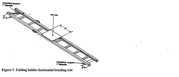
(33) "Folding ladder": a single ladder designed so that the rungs can be folded or moved in a manner to allow the beams to be brought into a position of touching each other, or nearly touching each other, for storage or carrying purposes.

(34) "Gauntlet": the circular, flared, or otherwise expanded part of the glove that extends beyond the opening of the glove body.

(35) "Goggles": the helmet component intended to help protect the wearer's eyes and a portion of the face.

(36) "GAWR": acronym for gross axle weight rating. The value specified as the load-carrying rating of a single axle system, as measured at the tire ground interfaces.

(37) "GCWR": acronym for gross combination weight rating. The value specified as the loaded weight of a combination vehicle.

(38) "GVWR": acronym for gross vehicle weight rating. The value specified by the chassis manufacturer as the loaded weight rating of a single vehicle.

(39) "Ground ladder": ladders not mechanically or physically attached permanently to fire apparatus and not requiring mechanical power from the apparatus for ladder use and operation.

(40) "Halyard": rope used on extension ladders for the purpose of raising the fly section(s). A wire cable may be referred to as a halyard when used on the uppermost fly section(s) of three or four section extension ladders.

(41) "Hard suction": a rubber-lined, rubber-covered hose whose reinforcement contains a semi-rigid or rigid helix to resist collapse under vacuum.

(42) "Hazardous atmosphere":

(a) Any atmosphere containing a toxic or disease-producing gas, vapor, dust, fume, or mist dangerous to the life or health or where the concentration is unknown; or

(b) Any atmosphere containing an oxygen partial pressure of less than 19.5 per cent by volume at sea level.

(43) "Hazardous environment": the area where members might be exposed to a particular substance, device, event, circumstance, or condition that presents a danger to members of the fire department.

(44) "Headband": the portion of a suspension system that encircles the head.

(45) "Heat sensor label": a label that turns color at a preset temperature to indicate a specific heat exposure.

(46) "Inside width": the distance measured from the inside edge of one beam to the inside edge of the opposite beam of a ladder.

(47) "Ladder belt": a belt intended for use as a positioning device for a person on a ladder. It fastens around the waist only.

(48) "Ladder/escape belt": a belt intended as both a ladder belt and an escape belt for use by the wearer only as an emergency self-rescue device. It fastens around the waist only.

(49) "Large-diameter supply hose": hose of three and one-half inch (eighty-nine millimeters) diameter or larger used to move large volumes of water.

(50) "Life safety harness": harness used to support persons during fire service rescue.

(a) Class I: harness that fastens around the waist and around thighs or under buttocks; designed to be used for emergency escape with a design load of three hundred foot-pounds (four hundred seven joules).

(b) Class II: harness that fastens around the waist and around the thighs or under the buttocks; designed for rescue with a design load of six hundred foot-pounds (eight hundred thirteen joules).

(c) Class III: harness that fastens around the waist, around the thighs or under the buttocks, and over the shoulders; designed for rescue with a design load of six hundred foot-pounds (eight hundred thirteen joules) that may be encountered and where inverting may occur.

(51) "Life safety rope": rope dedicated solely to the purpose of constructing lines for supporting persons during fire rescue, fire fighting, or during training activity.

(a) "Technical use": rope having a diameter of three-eighths inch (9.5 millimeters) or greater and less than one-half inch (thirteen millimeters).

(b) "General use": rope having a diameter of seven-sixteenths inch (thirteen millimeters) or greater and not more than five-eighths inch (sixteen millimeters).

(52) "Maximum extended length": the total length of an extension ladder or a combination ladder when all fly sections are fully extended and pawls engaged.

(53) "Optical warning device": a manufactured assembly of a single optical light emitter or a fixed array of any number of optical light emitters.

(54) "PASS": acronym for personal alert safety system. Devices that sense movement or lack of movement, and that automatically activate an audible alarm signal (which also can be manually activated) to alert and to assist others in locating a firefighter who is in danger.

(55) "Pawls": devices attached to fly sections for the purpose of anchoring fly sections, when extension ladders are used in the extended position. Pawls engage ladder rungs near the beams for anchoring purposes.

(56) "Permanent deformation": that deformation remaining in any part of a ladder or its components after all test loads have been removed from the ladder.

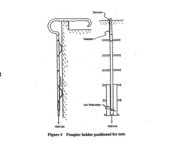
(57) "Pompier ladder": Also known as a "scaling ladder," a ladder having a single center beam only and with a large hook on top, used for scaling.

(58) "Prescribed fire": any fire ignited by management actions under certain predetermined conditions to meet specific land management objectives.

(59) "Protective hood": a garment worn under a helmet to protect the exposed portions of the head, face, and neck.

(60) "PTO": acronym for power takeoff.

(61) "Quantitative fit test": an assessment of the adequacy of respirator fit by numerically measuring the amount of leakage into the respirator.

(62) "Retention system": the complete assembly by which a helmet is retained in position on the head.

(63) "Retroreflective": describes material that reflects and returns a relatively high proportion of light in a direction close to the direction from which it came.

(64) "Roof ladder": a single ladder equipped with hooks at the top end of the ladder.

(65) "Rungs": the ladder crosspieces on which a person steps while ascending or descending.

(66) "Safety factor": the ratio between the ultimate breaking stress and the working stress of the material, structure, or device.

(67) "Self-contained breathing apparatus" or "SCBA": a device providing the wearer with a supply of respirable gas carried in or generated by the apparatus. When in use, this apparatus requires no intake of air from the environment in which the wearer is operating.

(a) "Closed circuit SCBA": an apparatus of the type in which the exhalation is rebreathed by the wearer after the carbon dioxide has been effectively removed and a suitable oxygen concentration restored.

(b) "Open circuit SCBA": an apparatus of the following types from which exhalation is vented to the atmosphere and not rebreathed:

(i) "Demand type": an apparatus in which the pressure inside the facepiece, in relation to the immediate environment, is positive during exhalation and negative during inhalation. This type of SCBA is prohibited by rule 4123:1-21-02 of the Administrative Code.

(ii) "Positive-pressure type": an apparatus in which the pressure inside the facepiece, in relation to the immediate environment, is positive during both inhalation and exhalation.

(68) "Service tests": tests to be performed on a regular basis after a ground ladder is in service to determine its suitability for service.

(69) "Shall": to be construed as mandatory.

(70) "Shell": the outermost part of a helmet.

(71) "Single ladder": a non-self-supporting ground ladder, non-adjustable in length, consisting of only one section.

(72) "Split shaft PTO": a PTO drive system that directs the chassis power either to the pump or to the chassis drive axle. This is accomplished by splitting the chassis driveline that connects the chassis transmission to the drive axle and inserting the split shaft PTO that has the shift mechanism necessary to direct the engine power as described above.

(73) "Stabilizer": a device integral with or separately attached to the chassis of an aerial fire apparatus that is used to increase the moments tending to resist overturning the apparatus.

(a) "Stabilizer pad": a plate inserted beneath a stabilizer shoe to give greater surface bearing area.

(b) "Stabilizer shoe": a permanently mounted shoe on a stabilizer to provide a ground surface area.

(74) "Staypoles": poles attached to each beam of the base section of extension ladders and used to assist in the raising of the ladder and to help provide stability to the raised ladder.

(75) "Structural fire fighting": the physical activity of fire rescue, fire suppression, or both, at buildings, enclosed structures, vehicles, vessels, or like properties that are involved in a fire or a situation where there is the potential for fire.

(76) "Supply hose": hose of three inch (seventy-six millimeter) diameter or larger designed for the purpose of moving water between a pressurized water source and a pump that is supplying attack lines.

(77) "Suspension system": an energy attenuating system made up of headband and crown straps.

(78) "Thermal protective performance": measurement of the amount of heat transfer through the protective ensemble from a thermal exposure equal to flashover conditions that results in second degree burn damage to the wearer's skin as related to the time of heat exposure.

(79) "Throwline": a floating one-person rope that is intended to be thrown to a person during water rescues or as a tether for rescuers entering the water.

(80) "Tip": as used with respect to ladders, the end of the beam opposite the butt.

(81) "Trouser" or "protective trouser": a garment worn to protect the lower part of the body, except the feet.

(82) "Ultimate failure": collapse of a ground ladder structure or component thereof.

(83) "Unlined hose": a hose, usually made of linen yarns, consisting of only the woven jacket, and having such qualities that the yarn of the jacket swells when wetted, tending to seal the hose. This type of hose is to be used primarily for wildland or forestry fires.

(84) "Water tower": a device consisting of permanently mounted, power-operated booms and a waterway designed to supply a large capacity mobile elevated water stream. The booms may be of articulating design or telescoping design and may be equipped with a ladder.

(85) "Wildland fire fighting": the activities of fire suppression and property conservation in woodlands, forests, grasslands, brush, prairies, and other such vegetation, or any combination of vegetation.

(86) "Wristlet": an attachment, fitted to the top of a glove or to the sleeve of a protective coat, to completely cover the wrist area under all conditions.

Last updated September 1, 2026 at 8:41 AM

Supplemental Information

Authorized By: 4121.12, 4121.121, 4121.13
Amplifies: 4121.13, Const. Art. II Section 35
Five Year Review Date: 9/1/2031
Prior Effective Dates: 1/1/1995, 1/1/2011
Rule 4123:1-21-02 | Personal protective clothing and equipment for structural fire fighting.
 

(A) The employer shall provide and require the use of personal protective clothing and equipment, as specified in this rule, when employees are required to work in a hazardous environment that may be encountered during structural fire fighting activities and under similar conditions during training activities in accordance with the most current edition of national fire protection association standard ("NFPA") 1970.

(B) The employer shall assure that protective clothing protects the head, body, and extremities and consists of at least the following components: foot protection; hand protection; body protection; eye, face, and head protection; and respiratory protection.

(C) Personal protective clothing and equipment shall be properly sized for the wearer.

(D) Personal protective clothing and equipment that is damaged or otherwise defective to the point of voiding its intended protection shall be removed from service.

(E) Employers shall develop and require use of a written plan covering the safe use, limitations, care, inspection, maintenance, and replacement of the clothing and equipment required by this rule, and all affected employees shall be trained in accordance with such plan.

(F) Employers shall develop and retain records for the life of the protective clothing and equipment.

(G) Employer shall provide for the cleaning of personal protective clothing.

(H) Where employees choose to provide their own protective clothing and equipment, such clothing and equipment shall give equal or greater protection than that provided by the employer.

(I) It shall be the responsibility of the employee to properly use the equipment provided by the employer, as required in this rule.

(J) Body protection.

(1) Body protection shall consist of a protective coat and trousers, or equivalent protection that are in accordance with the most current edition of NFPA 1970.

(2) Protective clothing shall be flame-resistant, durable, light-weight, water-resistant, nonirritating to the skin, and cleanable as set forth in paragraph (J) of this rule.

(3) Protective clothing shall be cleaned per the manufacturer's recommendations.

(4) Protective clothing for structural fire fighting shall be repaired in accordance with manufacturer's requirements. If protective clothing cannot be repaired properly without decreasing the protective qualities, the protective clothing shall be replaced.

(5) Protective clothing shall be designed in accordance with the most current edition of NFPA 2500 to give minimum interference to physical movement, the use of fire-fighting tools, and protective breathing apparatus.

(6) Employers that provide protective coats with protective resilient wristlets secured through a thumb opening shall be permitted to provide gloves with gauntlets for use with these protective coats. Employers that do not provide such wristlets attached to the protective coats shall provide gloves with protective resilient wristlets for use with these protective coats.

(K) Foot protection.

Protective footwear shall be capable of withstanding all tests specified in the most current edition of NFPA 1970.

(L) Head protection.

Head protection shall consist of a fire fighters' helmet and a protective hood that is in accordance with the most current edition of NFPA 1970. The helmet shall consist of a shell, an energy-absorbing system, a retention system, retroreflective and fluorescent markings, ear covers, and either a faceshield, or goggles, or both.

(M) Primary eye protection.

(1) Primary eye protection appropriate for a given specific hazard shall be provided for and used by employees exposed to that specific hazard.

(2) Primary eye protection shall meet the requirements of the most current edition of American national standards institute ("ANSI") Z87.1, practice for occupational and educational eye and face protection.

(3) The helmet faceshield, or flip-down eye shields, alone shall not be used as primary eye protection.

(4) The full facepiece of self-contained breathing apparatus ("SCBA"), with the regulator attached, shall constitute face and primary eye protection.

(N) Protective hood.

(1) The hood shall be designed to cover and provide the limited protection to the head, face, and neck areas that do not receive primary protection from the helmet or the SCBA facepiece.

(2) The hood shall be donned properly, in accordance with the manufacturer's instructions for wearing, and comply with the most current edition of NFPA 1970.

(O) Personal alert safety system ("PASS").

(1) Each employee shall be provided with, use, and activate their PASS device in all emergency situations that could jeopardize that person's safety due to atmospheres that could be immediately dangerous to life or health, incidents that could result in entrapment, structural collapse of any type, or as directed by the incident commander or incident safety officer.

(2) All PASS devices shall be capable of withstanding all performance tests specified in the most current edition of NFPA 1982.

(3) Each PASS device shall be tested at least weekly and prior to each use.

(4) Each PASS device shall be maintained in accordance with the manufacturer's instructions.

(5) PASS devices can be designed to be either a stand-alone PASS, or a SCBA-integrated PASS, which can be removable or non-removable.

(6) Each PASS shall incorporate data logging in nonvolatile memory, and at a minimum, the following events shall be identified and recorded with the data log and shall also have a date and time stamp for each event in the data log:

(a) When the PASS is turned on;

(b) When the PASS activates any alarm or pre-alarm;

(c) When the PASS alarm is activated by the user;

(d) When the PASS alarm was reset;

(e) When the PASS was turned off; and

(f) When the PASS low power source warning signal activates.

(7) The data logging information of each PASS shall be downloadable by the employer.

(8) Each PASS shall incorporate a mode selection device or devices to allow for operation in at least three modes: "Off," "Alarm," and "Sensing."

(a) All mode selection devices shall be capable of being switched to the alarm or sensing mode by a single gloved hand.

(b) Only one action shall be required to switch the mode selection device(s) from any mode to alarm.

(c) When a PASS is sounding the alarm signal it shall require at least two separate and distinct manual actions to silence the alarm signal.

(9) Each PASS shall be provided with a light source capable of providing a visual indication of mode status as well as an audible source capable of providing an aural indication of a change in the mode selection when switching from "off" to "sensing," "off" to "alarm," and "alarm" to "sensing."

(10) Each PASS shall incorporate a motion detector, and while in the sensing mode, shall sound the alarm signal when the PASS is motionless for thirty seconds, plus five/minus zero seconds. The alarm signal shall be preceded by a pre-alarm signal that shall sound no more than ten seconds, plus three/minus zero seconds, before the sounding of the alarm signal.

(a) The motion detector shall be operable regardless of the angle of deployment of the PASS.

(b) Any failure of the motion detector shall cause the PASS to sound the alarm signal within thirty seconds, plus five/minus zero seconds, of such failure.

(11) Each PASS shall emit an audible operational signal within one second of being switched to sensing mode, indicating to the user that the device is functioning properly.

(12) Each PASS shall have at least an audible primary pre-alarm signal. The primary pre-alarm signal shall be a distinct and different sound from the alarm signal. This signal shall sound no more than ten seconds prior to the sounding of the alarm signal.

(13) Each PASS shall sound the alarm signal when switched to the alarm mode. The alarm signal shall have a duration of at least one hour at a sound pressure level of not less than ninety-two decibels A-weighted (dBa).

(14) While in the sensing mode, each PASS shall emit a recurrent audible low power source warning signal when the battery voltage is depleted to the level that will maintain the alarm signal level of at least ninety-two decibels A-weighted (dBa) for at least one hour.

(15) This sound shall be distinct and different from the pre-alarm and alarm signals. The low power source warning signal shall have an interval of not greater than thirty seconds.

(16) The cancellation of the pre-alarm signal or the silencing of the alarm signal shall automatically reset the PASS to the sensing mode.

(17) PASS devices shall be capable of withstanding all performance requirement tests specified in the most current edition of NFPA 1982, "Personal Alert Safety Systems (PASS)."

(P) Respiratory protection.

(1) All fire fighters exposed to hazardous atmospheres from fires and other emergencies, or where the potential for such exposure exists, shall be provided SCBA approved by the national institute for occupational safety and health (NIOSH) and the NFPA.

(2) The employer shall adopt and maintain a respiratory protection program that addresses the selection, inspection, safe use, and maintenance of respiratory protection equipment, training in its use, and the assurance of air quality testing.

(3) All employees who might be required to use respiratory protection equipment shall be medically certified by a physician, or by a state of Ohio licensed health care professional who can perform medical evaluations under the supervision of a physician, on an annual basis. Medical certification can be obtained by a medical examination, or by using the medical questionnaire as referenced in 29 CFR 1910.134 Appendix C, 77 FR 46949, July 1, 2024.

(4) The facepiece seal capability of each employee qualified to use SCBA shall be verified by quantitative fit testing on an annual basis and whenever new types of SCBA or facepieces are issued. Each new employee shall be tested before being permitted to use SCBA in a hazardous atmosphere. Only employees with a properly fitting facepiece shall be permitted by the employer to function in a hazardous atmosphere with SCBA.

(5) Only SCBA with an approved service life of thirty minutes or more shall be considered acceptable.

(6) The following SCBAs shall be considered to meet the requirements of this rule:

(a) Open circuit SCBA of the positive-pressure type that operate only in the pressure demand mode.

(b) Open circuit SCBA of the positive-pressure type, equipped with an air flow control device for doffing and donning purposes only. Such air flow control device shall not permit the continued use of the SCBA in the demand mode after donning.

(c) Closed circuit SCBA with a rated service life of more than two hours and a minimum protection factor of five thousand, as determined by an acceptable quantitative fit test performed on each individual. Such SCBA are acceptable only when long-duration respiratory protection is deemed necessary by the employer. Closed circuit SCBA shall operate in the positive-pressure mode only.

(7) Open circuit SCBA approved by NIOSH for use in the demand mode or for use in both the demand mode and the pressure demand mode are prohibited.

(8) Breathing air used to fill SCBA cylinders shall meet the requirements specified in the most current edition of NFPA 1989, "Standard on Breathing Air Quality for Emergency Services Respiratory Protection."

(9) Breathing air quality shall be tested quarterly by an accredited testing laboratory and shall meet the requirements of paragraph (P)(8) of this rule. This provision shall also apply to vendor-supplied and other fire department-supplied compressed breathing air. The employer receiving supplied air shall require the suppliers to provide documentation that the air received has been tested quarterly and that it meets the requirements of paragraph (P)(8) of this rule. Written records shall be maintained by the employer.

(10) The employer shall not permit any known interference with the facepiece-to-face seal or with the operation of the exhalation valve on the full facepiece of an SCBA on employees who are exposed to hazardous atmospheres from fires and other emergencies or where the potential for such exposure exists.

(11) Respiratory equipment shall be inspected, maintained, and repaired in accordance with the manufacturer's recommendations. Maintenance shall include at least:

(a) A written record of such inspection and maintenance for each piece of equipment, and

(b) Regulator calibration performed by a manufacturer-authorized person at no more than twelve-month intervals.

(12) All compressed air cylinders used with self-contained breathing apparatus shall meet department of transportation (DOT) and NIOSH criteria.

(13) SCBA cylinders shall be hydrostatically tested within the periods specified by the manufacturer, DOT, and NIOSH.

(14) The practice of buddy breathing, also known as universal emergency breathing safety system ("UEBSS"), may be utilized where it is accomplished through the use of an NFPA and NIOSH-approved connection that does not compromise the system integrity of either of the users giving or receiving air.

(15) The use of a universal air connection for rapid refilling of SCBA while being worn by the user shall only be done under the following conditions:

(a) Manufacturer permitted, NIOSH-approved fill options are used;

(b) An imminent life threatening situation occurs that requires immediate action to prevent the loss of life or serious injury;

(c) Prior to a life threatening situation occurring that could require immediate action to prevent the loss of life or serious injury; and

(d) The risk assessment process has identified procedures for limiting personnel exposure during the refill process and has provided for adequate equipment inspection and member safety.

(Q) Hand protection.

(1) Hand protection shall consist of properly sized protective gloves or a glove system which allows dexterity of hand movement and a sense of feel for objects.

(2) Gloves of the wristlet type or other interface component shall be required if the protective coat does not provide a protective resilient wristlet with a thumb opening.

(3) Gloves of the gauntlet type shall be allowed if the protective coat provided has a protective resilient wristlet with a thumb opening.

(4) Gloves shall be maintained and repaired in accordance with the manufacturer's requirements. If gloves cannot be repaired properly without decreasing the protective qualities required by this rule, they shall be replaced with gloves that meet the requirements of this rule.

(5) The manufacturer's label shall remain permanently attached to each glove unaltered.

(R) Fall protection.

(1) Life safety rope.

(a) Technical use life safety rope shall have a diameter of three-eighths inch (9.5 millimeters) or greater and less than one-half inch (12.7 millimeters). It shall have a minimum breaking strength of not less than four thousand four hundred ninety-six foot-pounds (6.1 kilojoules). The minimum elongation shall be less than one per cent at ten per cent of breaking strength, and the maximum elongation shall not be more than ten per cent at ten per cent of breaking strength.

(b) General use life safety rope shall have a diameter seven-sixteenths inch (eleven millimeters) or greater and not more than five-eighths inch (sixteen millimeters). It shall have a minimum breaking strength of not less than eight thousand nine hundred ninety-two foot-pounds (12.2 kilojoules). The minimum elongation shall not be less than one per cent at ten per cent of breaking strength, and the maximum elongation shall not be more than ten per cent at ten per cent of breaking strength.

(c) Life safety rope shall be constructed of virgin fiber and shall be of block creel construction. Load-bearing elements shall be constructed of continuous filament fiber.

(d) Fiber used for life safety rope shall have a melting point of no less than four hundred degrees Fahrenheit (204.4 degrees Celsius).

(e) Each life safety rope shall have a product label that states the life safety rope meets the requirements of the most current edition of NFPA 2500. The label shall be permitted to be a hang tag affixed to each individual life safety rope or shall be permitted to be printed on a sheet that is inserted and sealed in the packaging that contains the life safety rope.

(f) In addition to the product label specified in this rule, each life safety rope shall be marked for its full length by insertion of a continuous identification tape. At least a statement indicating the rope meets the requirements for life safety rope of the most current edition of NFPA 2500 shall be legibly printed on the tape not less than once every thirty-nine inches (one meter):

(g) Life safety rope shall be inspected after being used for rescue at fires or other emergency incidents or for training. It may be reused if inspected before and after each such use in accordance with the manufacturer's instructions and provided that the rope:

(i) Has not been visually damaged by exposure to heat, direct flame impingement, chemical exposure, or abrasion;

(ii) Has not been subjected to any impact load;

(iii) Has not been exposed to chemical liquids, solids, gases, mists, or vapors of any material known to deteriorate rope; and

(iv) Passes inspection when inspected by a qualified person following the manufacturer's inspection procedures.

(2) Life safety harness.

(a) Life safety harnesses shall be designed and designated in accordance with one of the following classes:

(i) Harness that fastens around the waist and around thighs or under buttocks and designed for rescue with a design load of six hundred foot-pounds (0.8 kilojoules)shall be designated as class II life safety harness.

(ii) Harness that fastens around waist, around thighs or under buttocks, and over shoulders, designed for rescue with a design load of six hundred foot-pounds (0.8 kilojoules) shall be designated as class III life safety harness. Class III life safety harness shall be permitted to consist of one or more parts.

(b) Life safety harness shall have at least one load bearing attachment point located at the front waist or sternal location of the harness.

(c) Each life safety harness shall have permanently affixed a product label embossed, printed, sewn, stapled, riveted, or otherwise permanently attached with a metal label plate that at minimum, identifies the class of the life safety harness and indicates the life safety harness is in compliance with the harness requirements of the most current edition of NFPA 2500.

(d) Each life safety harness shall be capable of withstanding all tests specified in the most current edition of NFPA 2500.

(e) Where class II and III life safety harness include side "D-rings" and attachment points designated by the manufacturer as positioning attachments only, these attachments shall show no visible signs of damage that affect its function.

(3) Belt system.

(a) Belts shall be designed and designated in accordance with one of the following types:

(i) A belt that fastens only around the waist and is intended for use as a positioning device for a person on a ladder shall be designated as a ladder belt.

(ii) A belt that fastens only around the waist and is intended for use as a positioning device for a person on a ladder and also intended for use only by the wearer as an emergency self-rescue device shall be designated as a ladder/escape belt.

(b) All belts shall be permitted to be adjustable within a range of sizes, provided in a range of sizes, or custom-fitted for individuals.

(c) Load-bearing textile materials used in the construction of all belts shall be made of virgin, synthetic, continuous filament fiber.

(d) All belts shall have webbing ends secured by heat sealing or by another method that prevents unraveling.

(e) All thread utilized in the construction of all belts shall be compatible with the webbing used and shall allow for ease of inspection.

(f) The ladder belt tether or device that connects the wearer to a ladder shall be permanently affixed to the ladder belt and shall not be greater than twenty-four inches (six-hundred ten mm) in length. This requirement applies only to ladder belts.

(g) Each belt shall have permanently affixed a product label embossed, printed, sewn, stapled, riveted, or otherwise permanently attached with a metal plate.

(h) All ladder belts and ladder/escape belts shall be capable of withstanding all tests specified in the most current edition of NFPA 2500.

(4) Auxiliary equipment.

(a) Auxiliary equipment shall be designated by the manufacturer for its intended use and design load as either escape, technical use, or general use.

(i) Escape shall apply to equipment intended for the sole use of the rescuer for personal escape or self-rescue.

(ii) Technical use shall apply to equipment intended for a design load of three hundred foot-pounds (0.4 kilojoules).

(iii) General use shall apply to equipment intended for design loads of six hundred foot-pounds (08 kilojoules).

(b) Load-bearing hardware shall be constructed of forged, machined, stamped, extruded, or cast metal. Castings shall meet Class I, Grade A requirements of the most current edition of SAE AMS 2175A, "Castings, Classification and Inspection of."

(c) Rope grab devices shall be designated for either technical use or for general use.

(d) All load-bearing buckles shall have been proof loaded to at least two thousand four hundred seventy-three foot-pounds (3.6 kilojoules).

(e) Snap-link and carabiner gates shall be self-closing and of a locking design.

(f) Each item of auxiliary equipment shall be permitted to have a hang tag affixed to each individual auxiliary equipment item or shall be permitted to be printed on a sheet that is inserted and sealed in the packaging that contains the item.

(i) Auxiliary equipment shall also be stamped, engraved, or otherwise permanently marked with a "G" for general use; "T" for technical use; or "E" for escape.

(ii) Rigging and anchor straps shall indicate on the product label that minimum breaking strength and rating are determined using a basket (U) configuration.

(iii) Where detachable components must be used with the auxiliary equipment in order for the auxiliary equipment to be compliant, the product label shall provide the list of additional components to be used in conjunction with the auxiliary equipment to be compliant with the most current edition of NFPA 1983.

(g) All auxiliary equipment shall be capable of withstanding all tests specified in the most current edition of NFPA 2500.

(h) The employer shall furnish the employee using the auxiliary equipment with use criteria, inspection procedures, maintenance procedures, and retirement criteria for the product.

(5) Escape rope.

(a) Escape rope shall have a minimum breaking strength of not less than three thousand thirty-four foot-pounds (4.1 kilojoules).

(b) Elongation of all new escape rope shall be less than one per cent and not more than ten per cent at ten per cent of breaking strength.

(c) The employer shall furnish the employee using the escape rope with use criteria, inspection procedures, maintenance procedures, and retirement criteria.

(6) Throwline.

(a) Throwline shall be constructed of virgin fiber and shall be of block creel construction. Load-bearing elements shall be constructed of continuous filament fiber.

(b) Throwline shall have a diameter of nineteen sixty-fourths inch (7.5 millimeters) or greater, but less than three eighths inch (9.5 millimeters).

(c) The minimum breaking strength for new throwline shall not be less than two thousand nine hundred twenty-three foot-pounds (four kilojoules).

(d) New throwline shall be tested for the ability to float and shall float.

(e) Each throwline shall meet the throwline requirements of the most current edition of NFPA 2500.

Last updated September 1, 2026 at 8:43 AM

Supplemental Information

Authorized By: 4121.12, 4121.121, 4121.13
Amplifies: 4121.13, Const. Art. II Section 35
Five Year Review Date: 9/1/2031
Prior Effective Dates: 3/1/1988, 11/1/2003, 6/1/2005, 6/11/2021
Rule 4123:1-21-03 | Personal protective clothing and equipment for wildland fire fighting.
 

(A) The employer shall provide and require the use of all personal protective clothing and equipment specified in this rule whenever employees are required to work in a hazardous environment that may be encountered during wildland fire fighting activities, prescribed fire activities, or under similar conditions during training activities.

(B) The employer shall assure that protective clothing protects the head, body, and extremities and consists of at least the following components: foot protection, hand protection, body protection, and head and eye protection.

(C) Personal protective clothing and equipment shall be properly sized for the wearer.

(D) Personal protective clothing and equipment that is damaged or otherwise defective to the point of voiding its intended protection shall be removed from service.

(E) Employers shall develop and require use of a written plan covering the safe use, care, maintenance, inspection, limitations, and replacement of the clothing and equipment required by this rule, and all affected employees shall be trained in accordance with such plan.

(F) Where employees choose to provide their own protective clothing and equipment, such clothing and equipment shall give equal or greater protection than that provided by the employer.

(G) It shall be the responsibility of the employee to properly use the equipment provided by the employer as required in this rule.

(H) Body protection.

(1) Body protection shall consist of a protective coat and protective trousers, or equivalent protection.

(2) Protective clothing shall be melt-resistant, durable, lightweight, nonirritating to the skin, and cleanable.

(3) The protective coat shall have long sleeves and shall not have turned-up cuffs. Sleeve cuffs shall have a closure system that can be adjusted to provide a snug and secure fit around the wrist while wearing a glove.

(4) All collars on jackets, shirts, and one-piece garments shall remain upright after extension into a vertical position.

(5) Any pass-through openings in garments shall have a means of fastening them in a closed position.

(6) All pockets that open to the exterior of garments, other than front waist pockets, shall have a cover or closure system.

(7) All garments that encompass the neck area shall have a closure system at the neckline.

(8) All closure systems shall not come into contact with the body. Hardware of any garment shall not come into direct contact with the wearer's body.

(9) Protective clothing for wildland fire fighting shall be repaired in accordance with manufacturer's requirements. If protective clothing cannot be repaired without decreasing the protective qualities, the protective clothing shall be replaced.

(10) Protective clothing shall be designed to give minimum interference to physical movement and to the use of fire-fighting tools.

(11) Where wildland fire fighting protective clothing is required, a fire shelter shall be provided.

(12) Protective clothing shall be capable of withstanding all tests specified in the most current edition of national fire protection association standard ("NFPA") 1950.

(13) The employer shall provide a user manual that describes the care, use, inspection, maintenance, limitations, and replacement of protective clothing.

(I) Foot protection.

(1) Foot protection shall be achieved by protective workstyle boots worn in combination with protective trousers that meet the requirements of the most current edition of NFPA 1950.

(2) Protective footwear meeting the requirements of paragraph (K) of rule 4123:1- 21-02 of the Administrative Code shall be considered to be in compliance with this rule.

(3) Performance requirements.

Footwear shall be capable of withstanding all tests specified in the most current edition of NFPA 1950.

(4) The employer shall provide a user information guide that describes the care, use, inspection, maintenance, limitations, and replacement criteria.

(J) Head protection.

(1) Wildland fire fighters' helmets shall consist of a shell with brim or peak, an energy-absorbing system, suspension system with sweatband, chin strap, nape device, goggle clips, and retroreflective markings. Provisions shall be made for ventilation between the head and the shell.

(2) Helmets shall meet as a minimum the requirements for type 1, class G helmets as specified in themost current edition of American national standards institute ("ANSI") Z89.1, "Industrial Head Protection." The complete helmet, with energyabsorbing system, suspension system with sweatband, chin strap, nape device, goggle clips, and retroreflective markings shall not weigh more than twenty-seven ounces (seven hundred seventy grams).

(3) Chin straps shall be provided that attach to the shell. Both chin and nape straps shall not be less than one-half inch (thirteen millimeters) in width.

(4) All helmets shall have retroreflective markings on the exterior of the shell. A minimum of four square inches (6.4 square centimeters) of retroreflective markings shall be visible when the helmet is viewed from the sides, front, and rear. The retroreflective markings shall be placed above the goggle or headlamp clips so as not to be obscured by any clip, or the strap retained by the clips.

(5) There shall be no openings penetrating the shell except those provided by the manufacturer for mounting energy-absorbing systems, retention systems, and accessories.

(6) The addition of helmet accessories shall not interfere with the function of the helmet or its component parts and shall not degrade the helmet's performance below the requirements of this rule.

(7) Helmets shall be capable of withstanding all tests specified in the most current edition of NFPA 1977, "Protective Clothing and Equipment for Wildland Fire Fighting."

(8) The employer shall provide a user information guide that describes the care, use, inspection, maintenance, limitations, and replacement criteria.

(9) Eye protection shall be provided by goggles. Goggles may be attached to the helmet.

(K) Hand protection.

(1) Gloves shall be designed such that they closely conform to the wrist or are adjustable at the wrist and shall extend a minimum on one inch (twenty-five millimeters) past the wrist crease.

(2) All thread used to manufacture gloves shall be made of inherently flame-resistant fiber.

(3) Gloves shall be maintained and repaired in accordance with the manufacturer's requirements. If gloves cannot be repaired properly without decreasing the protective qualities required by this rule, they shall be replaced with gloves that meet the requirements of this rule.

(4) The employer shall provide a user information guide that describes the care, use, inspections, maintenance, limitations, and replacement criteria.

(L) Face/neck shroud.

(1) Face/neck shrouds shall be designed to cover and provide the limited protection to the face and neck areas that do not receive primary protection from the helmet.

(2) The shroud shall attach to a helmet compliant with the most current edition of NFPA 1950.

(3) Shrouds shall have a closure system. The closure system shall not come into contact with the face or neck.

(4) The employer shall provide a user information guide that describes the care, use, inspection, maintenance, limitations, and replacement criteria.

(M) Protective goggles.

(1) Goggles shall be designed to consist of at least a frame, a lens or lenses, and a retention strap or means of attachment to a helmet compliant with the most current edition of NFPA 1950.

(2) Goggles shall meet the requirements for high impact protection of the most current edition of ANSI Z87.1, "Occupational and Educational Eye and Face Protection."

(3) All materials in goggle construction that are designed to come in contact with the wearer's head or skin shall be known to be nonirritating to normal skin.

(4) All hardware shall be free of rough spots, burrs, or sharp edges.

(5) Where positioned on the helmet, the goggles shall not interfere with the function of the helmet or its component parts and shall not degrade the helmet's performance below the requirements of this rule.

(6) The employer shall provide a user information guide that describes the care, use, inspection, maintenance, limitations, and replacement criteria.

(N) Chain saw protector.

(1) Chain saw protectors shall be designed as leg protectors and the most current edition of American society for testing and materials ("ASTM") F 1897.

(2) Chain saw protectors shall be capable of withstanding all tests specified in the most current edition of NFPA 1950.

(3) The employer shall provide a user information guide that describes the care, use, inspection, maintenance, limitations, and replacement criteria.

(O) Load carrying protective equipment.

(1) The load carrying protective equipment items shall allow the mounting of the fire shelter carrier on the outside as to be readily available to the user and able to be opened with one gloved hand.

(2) The load carrying protective equipment items shall allow the carrying of the employees' personal water supply in the form of canteens, water bottles, or bladders.

(3) All hardware, brackets, and snaps or other fasteners of any accessories shall be free of rough spots, burrs, or sharp edges.

(4) Load carrying protective equipment shall be capable of withstanding all tests specified in NFPA 1950.

(5) The employer shall provide a user information guide that describes the use, care, inspection, maintenance, limitations, and replacement criteria.

(P) Fire protective shelter.

(1) The fire shelter shall be enclosed in a carrying case liner, and the fire shelter and the carrying case liner shall be enclosed in a carrying case. The fire shelter, carrying case liner, and carrying case shall conform to the most current edition of NFPA 1500.

Last updated September 1, 2026 at 8:43 AM

Supplemental Information

Authorized By: 4121.12, 4121.121, 4121.13
Amplifies: 4121.13, Const. Art. II Section 35
Five Year Review Date: 9/1/2031
Prior Effective Dates: 3/1/1988
Rule 4123:1-21-04 | Automotive fire apparatus.
 

(A) New fire appartaus shall meet the requirements of the most current edition of the applicable national fire protection association standard ("NFPA") 1990.

(B)

(1) Two copies of a complete operation and maintenance manual covering the completed apparatus, including but not limited to the following, shall be available:

(a) The truck, pump, wiring and piping diagrams;

(b) Lubrication charts;

(c) Operating instructions for the chassis and any major component such as pump or aerial device or other fire fighting equipment;

(d) Precautions related to multiple configurations of aerial devices;

(e) Instructions regarding the frequency and procedure for recommended maintenance; and

(f) Parts replacement information.

(2) Also, all manufacturers' operations and maintenance documents supplied with components and equipment that are installed by the employer shall be supplied and made available:

(C) GAWR, GCWR, and GVWR, adequate to carry a full water tank, other tanks full, the specified hose load, ground ladders, personnel weight, and miscellaneous equipment allowance, shall be provided on the apparatus.

(D) Automatic engine shutdown systems are prohibited unless they are an integral part of the standard engine management system, which cannot be disabled.

(E) An engine speed control device shall be installed to allow an increase in the engine speed when the apparatus is parked. An interlock shall prevent the operation of this engine speed control device unless the parking brake is fully engaged and the transmission is in neutral or park, or the parking brake is engaged and the engine is disengaged from the drive wheels.

(F) Fuel system, gasoline or diesel.

(1) The fuel line(s) shall be so located or protected as not to be subjected to excessive heating from any portion of a vehicle exhaust system. The line(s) shall be protected from mechanical injury.

(2) Fuel tank and fill piping shall be so placed as to be protected from mechanical injury and shall not be exposed to heat from exhaust or other source of ignition.

(3) The tank fill opening shall be marked with a label indicating the proper fuel.

(G) Exhaust system, gasoline or diesel.

(1) The exhaust piping and discharge outlet shall be so located as not to expose any portion of the apparatus or equipment to excessive heating.

(2) Exhaust pipe discharge shall not be directed toward any employee's position.

(3) Silencing devices shall be provided.

(4) When parts of the exhaust system are exposed to operating personnel, protective guards shall be provided.

(5) If the apparatus is equipped with stabilizers, the exhaust piping discharge shall be directed away from the contact area between the stabilizer and the ground when the stabilizer is deployed.

(H) Low voltage (twelve/twenty-four volt) electrical system and warning devices.

(1) All electrical circuit wiring shall be made with stranded conductors of a carrying capacity of one hundred twenty-five per cent of the anticipated maximum circuit loading. Insulation shall be in accordance with the recommended standards of the society of automotive engineers ("SAE") for such loading at the potential employed. Overall covering of conductors shall be of the moisture-resistant type and have a minimum continuous temperature rating of one hundred ninety-four degrees Fahrenheit (ninety degrees Celsius). All connections shall be made with lugs or terminals mechanically secured to the conductors. Wiring shall be restrained to prevent damage caused by chafing or ice buildup and protected against heat, liquid contaminants, or other environmental factors.

(2) Circuits shall be provided with overload protective devices. Such devices shall be readily accessible and protected against heat, physical injury, and water spray.

(3) Power supply.

(a) A twelve volt or greater electrical alternator shall be provided. It shall have a minimum output at idle to meet the minimum continuous electrical load of the apparatus as defined in the most current edition of NFPA 1900 at two hundred degrees Fahrenheit (ninety-three degrees Celsius) ambient temperature within the engine compartment and shall be provided with full automatic regulation.

(b) The condition of the low-voltage electrical system shall be monitored by a system that provides an audible and visual warning to the driver or operator of the apparatus.

(c) A voltmeter shall be mounted on the driver's instrument panel to allow direct observation of the system voltage.

(d) If the total continuous electrical load exceeds the minimum continuous electrical output rating of the installed alternator(s) operating under the conditions specified in this rule, an automatic electrical load management system shall be required.

(4) Batteries.

Batteries shall be securely mounted and protected against physical injury and vibration, water spray, and engine and exhaust heat. When an enclosed battery compartment is provided, the battery compartment shall be adequately ventilated, and the batteries shall be readily accessible for examination, test, and maintenance.

(5) Lights and warning devices.

(a) The rear stop, tail, and directional lights shall be so mounted that they will not be obscured by equipment carried on the rear step. Turn signals shall be visible from front, sides, and rear. On apparatus thirty feet (9.1 meters) or longer in length, a turn signal shall be mounted approximately midway along the apparatus at approximately running board height.

(b) All apparatus shall have upper and lower optical warning devices. The upper and lower warning levels shall each be divided into four warning zones. The four zones shall be determined by drawing lines through the geometric center of the apparatus at forty-five degrees to a line lengthwise of the apparatus through the geometric center. The four zones shall be designated A, B, C, and D in a clockwise direction with zone A to the front of the apparatus. See figure 1.
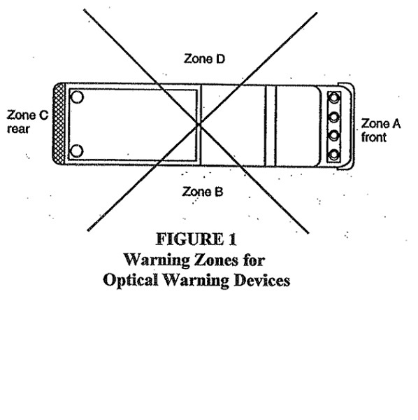
Figure 1 depicts warning zones for optical warning devices on fire apparatus to ensure visibility in all directions divided into four zones, created by drawing an X through the center of the vehicle. The zones are labeled A through D in a clockwise direction, beginning with Zone A as the zone for the front of the vehicle.

(i) The front optical warning devices shall be placed so as to maintain the maximum possible separation from the headlights.

(ii) A midship optical warning device shall be mounted on both the right and left sides of the apparatus with the optical center of the device at a distance between eighteen and sixty-two inches (45.7 and 157.5 centimeters) above level ground if the distance between the front and rear lower-level optical devices exceeds twenty-five feet (7.6 meters).

(c) Apparatus shall have hooded lights, with individual switches, providing illumination of the pump operating panel, tool and equipment compartments, steps, and walkways. Switches shall be located within easy reach of the operator.

(d) The work area immediately behind the vehicle shall be illuminated to a level of at least three footcandles (thirty lux) within ten feet (three meters) by ten feet (three meters) square to the rear of the vehicle. If a hose bed is provided, lighting on this hosebed shall be at a level of three footcandles (thirty lux) or higher.

(e) The apparatus shall be equipped with lighting that is capable of providing illumination at a minimum level of two footcandles (twenty lux) on the ground area within thirty inches (76.2 centimeters) of the edge of the apparatus in areas designed for personnel to climb onto or descend from the apparatus to the ground level. Lighting designed to provide illumination on areas under the driver and crew riding area exits shall be activated automatically when the exit doors are opened. All other ground area lighting shall be switchable.

(f) A red flashing or rotating light, marked with a sign that clearly states to not move the apparatus when the light is on, located in the driving compartment, shall be illuminated automatically whenever the apparatus's parking brake is not fully engaged and any of the following conditions exist:

(i) Any passenger or equipment door is open.

(ii) Any ladder or equipment rack is not in the stowed position.

(iii) Stabilizer system not in its stowed position.

(iv) Powered light tower is extended.

(v) Any other device is opened, extended, or deployed that creates a hazard or is likely to cause damage to the apparatus if the apparatus is moved.

(g) Audible warning equipment in the form of one automotive horn and one electric or electronic siren shall be provided. Control for operating the siren shall be provided for the right and left seat positions.

(h) Where furnished, air horns, electric siren(s), and electronic siren speaker(s) shall be mounted as low and as far forward on the apparatus as practical. Audible warning equipment shall not be mounted on the roof of the apparatus.

(i) An electric or electronic backup alarm shall be provided that meets the type D (eighty-seven decibels A-weighted) requirements of the most current edition of SAE J994.

(I) Vehicle components.

(1) Line voltage (one hundred ten/two hundred twenty volts).

(a) The generating system shall be installed in accordance with the grounding requirements of section 250-34 of the most current edition of NFPA 70, "National Electric Code."

(b) When receptacles or other facilities providing one hundred ten volt alternating current ("AC") or direct current ("DC") power are installed, such receptacles and other facilities shall be of the weatherproof type, and all circuits or associated wiring shall have at the source of one hundred ten volt supply overload protection rated at the carrying capacity of the conductor. Circuits shall be three-wired and installed in accordance with section 250-34 of the most current edition of NFPA 70. Those receptacles shall conform to the appropriate national electrical manufacturers association configuration for the voltage and capacity of the circuit.

(c) All fixed auxiliary engine-driven generators shall comply with article 445, "Generators," of the most current edition of NFPA 70, national electrical code.

(i) They shall be installed so that fumes, vapors, heat, and vibrations do not enter the interior passenger compartment.

(ii) They also shall have the exhaust outlet piped to the exterior and located so that exhaust is directed away from any operator's position.

(iii) Where parts of the exhaust system are exposed so that they can cause injury to operating personnel, protective guards shall be provided.

(d) Portable generator installations shall comply with article 445, "Generators," of the most current edition of NFPA 70.

(e) If the apparatus is equipped with a fixed power inlet, also known as a shoreline inlet, it shall be a permanently mounted, flanged surface inlet, also known as a male-recessed-type receptacle with cover, sized in accordance with the anticipated load and wired directly to the system or device to be powered; or wired to a transfer switch to isolate one power source from the other where one or more circuits are intended to be supplied from more than one power source.

The apparatus shall have a label permanently affixed at the power inlet.

(2) Braking system.

(a) Apparatus shall be equipped with an all-wheel antilock braking system if such system is available from the chassis manufacturer.

(b) Service and parking brakes shall be independent and separate systems. All brakes shall be readily accessible for adjustment.

(c) The service brake application valve, when applied, shall operate all the service brakes on the vehicle or combination of vehicles.

(d) Parking brakes shall control the rear wheels, or all wheels, and shall be of a positive, mechanically actuated type with provision for securely holding in position when applied. The parking brake system shall hold the fully loaded apparatus on at least a twenty per cent grade. Neither a lock-up device to retain applied pressure on hydraulically actuated service brake system, nor a "park" position on an automatic transmission as a substitute for a separate parking brake system, is acceptable.

(e) Where air-actuated braking systems are provided, they shall include the following:

(i) An automatic moisture ejector;

(ii) An air dryer;

(iii) A pressure protection valve to prevent the use of all air-operated accessories except air-operated windshield wipers and air-assist steering, if provided, when the system air pressure drops below eighty pounds per square inch (five hundred fifty kilopascals);

(iv) A quick buildup section in the air reservoir system arranged so that if the apparatus has a completely discharged system, it is able to move within sixty seconds of startup.

(a) The quick buildup system shall provide sufficient air pressure so that the apparatus has no brake drag and is able to stop under the intended operating conditions following the sixty second buildup time.

(b) On a chassis that cannot be equipped with a quick buildup air brake system, an onboard automatic electric compressor or a fire station compressed air shoreline hookup shall be permitted in order to maintain full operating air pressure while the vehicle is not running.

(f) Two or more wheel chocks, mounted in readily accessible locations, that meet or exceed the requirements of the most current edition of SAE J348, "Standard for Wheel Chocks," for the wheel diameter on which the chocks are to be used, shall be provided and used when the apparatus is not being driven but being operated in a stationary position.

(g) Service brakes shall be capable of bringing a fully laden apparatus to a complete stop from an initial speed of twenty mph (thirty-two kilometers per hour) in a distance not exceeding thirty-five feet (10.7 meters) by actual measurement on a substantially hard surface road that is free from loose material, oil, or grease.

(3) Suspension and wheels.

(a) Each load-bearing tire and rim of the apparatus shall carry a weight not in excess of the tire manufacturer's rating.

(b) An angle of approach and an angle of departure of at least eight degrees shall be maintained at the front and rear of the vehicle when normally loaded.

(c) Fenders and guards shall be braced and firmly secured.

(d) The steering mechanism for front axles shall be capable of turning the front wheels to an angle of at least twenty-eight degrees front axles and thirty degrees for nondriving front axles to both right and left. Power or power-assisted steering shall be provided.

(4) Body.

(a) A bumper shall be provided on the front of the chassis, and the bumper mounting brackets shall be attached to the frame.

(b) Holders, boxes, compartments, or other attachments shall be provided for all tools, equipment, play-pipes, and other items on the apparatus. Equipment holders shall be firmly attached and designed so that equipment will remain in place under all running conditions but be quickly removable for use.

(c) Steps, platforms, or secure ladders shall be provided so that employees have access to all working and storage areas of the apparatus. The maximum stepping height shall not exceed eighteen inches (45.7 centimeters) with the exception of the ground to first step. When the ground to first step, platform, or ladder rung exceeds twenty-four inches (sixty-one centimeters), a permanently attached supplemental means of access and egress from the ground to these steps, platforms, or secure ladders shall be provided. The supplemental access means shall consist of step(s), platform(s), or ladder(s). The ground to first step height shall be determined with the apparatus on level ground. When the apparatus is supplied with stabilizers, the ground to first step height shall be determined with the apparatus on level ground and the stabilizers deployed according to the manufacturer's instructions.

(i) All steps, platforms, or ladders shall be capable of sustaining a minimum static load of five hundred pounds (226.8 kilograms) without deformation.

(ii) All exterior surfaces designated as stepping, standing, and walking areas shall have a minimum average slip resistance of 0.68 in accordance with the most current edition of American society for testing and materials ("ASTM") E303 or American national standards institute ("ANSI") A326.3 for current slip resistance benchmarks. All interior steps shall provide an average minimum slip resistance of 0.58. Where the fuel fill is located at or near a stepping surface, the surface shall be constructed of an open grate-type material.

(iii) All steps shall have a minimum area of thirty-five square inches (225.8 square centimeters) and be arranged to provide at least eight inches (20.3 centimeters) of clearance between the front of the step and any obstruction. All ladders shall have at least eight inches (20.3 centimeters) of clearance between any rung and the body of the apparatus.

(d) Access handrails shall be provided at all entrances to the driving or crew compartment and at any location where the employee is required to climb up on the apparatus for access to equipment. Exterior access handrails shall be constructed of a slip-resistant, non-corrosive material. Rails shall be between one inch (2.5 centimeters) and one and five-eighths inches (4.1 centimeters) in diameter and have a minimum clearance between the rails and any surface of at least two inches (5.1 centimeters). All rails shall be designed and mounted to reduce the possibility of hand slippage and to avoid snagging of hose, equipment, or clothing.

(e) A reflective stripe(s) shall be affixed to the perimeter of the apparatus. The stripe or combination of stripes shall be a minimum of four inches (10.2 centimeters) in total width and shall conform to the minimum requirements of the most current edition of ASTM D 4956. At least fifty percent of the cab and body length on each side, at least fifty percent of the width of the rear, and at least twenty-five percent of the width of the front of the apparatus shall have the reflective material affixed to it. A graphic design meeting the reflectivity requirements of this paragraph shall be permitted to replace all or part of the required striping material if the design or combination thereof covers at least the same perimeter length(s) required within.

(5) Driving and crew compartment.

(a) A fully enclosed driving or crew compartment with seating for no fewer than two persons shall be provided. Seat belts shall be provided and shall be utilized by each occupant of the cab.

(b) In wildland fire fighting, employees shall be required to ride within a fully enclosed personnel area.

(c) The noise in the compartment shall not be in excess of ninety decibels A-weighted without any warning devices in operation and while the vehicle is traveling at a steady speed of forty-five miles per hour (72.4 kilometers per hour) on a level, hard, smooth surface road.

(d) All interior crew and driving compartment door handles shall be designed and installed to protect against accidental or inadvertent opening.

(e) Head height at any suspension-style seat shall be at least thirty-seven inches (ninety-four centimeters) from the seat H-point to the ceiling. For nonsuspension-style seats it shall be thirty-five inches (88.9 centimeters). Each seating space shall have a minimum width of twenty-two inches (55.9 centimeters) at the shoulder level. Seat cushions shall be a minimum of eighteen inches (45.7 centimeters) in width and fifteen inches (38.1 centimeters) from the front of the cushion to the face of the seat back. A back cushion that extends from the face of the seat vertically at least eighteen inches (45.7 centimeters) and that is a minimum of eighteen inches (45.7 centimeters) wide shall be provided. The back cushion shall be permitted to be split to accommodate a fully recessed self-contained breathing apparatus ("SCBA") and bracket. Where the back cushion is split, a headrest shall be supplied.

(f) Where SCBA units are mounted within the crew compartment, a positive, mechanical means of holding the SCBA in its stowed position shall be provided. The bracket holding device and its mounting shall retain the SCBA unit when subjected to a nine-G force and shall be installed in accordance with the bracket manufacturer's requirements. If the SCBA cylinder is mounted in a vertical position with the valve down, it shall be supported with a brace or yoke under the cylinder or valve area to prevent downward movement.

(g) All equipment within the driving or crew area shall be securely fastened. All equipment not required to be used during an emergency response, with the exception of SCBA units, shall be contained in a fully enclosed and latched compartment, or mounted in at least one bracket that is capable of containing the contents when a nine-G force is applied in the longitudinal axis of the vehicle or a three-G force is applied in any other direction.

(h) The driver's seat shall be readily adjustable by the driver.

(i) Where the crew compartment and the driving compartment are separated, prohibiting direct voice communication, a two-way voice communication system shall be provided.

(j) A speedometer and odometer shall be provided.

(k) All driving and crew compartment doors shall have at least ninety-six square inches (619.4 square centimeters) of reflective material affixed to the inside of each door.

(l) The apparatus shall have sufficient lighting to provide an average level of two footcandle (twenty lux) in the driving and crew compartments.

(m) Each engine compartment and pump compartment shall have a light of at least twenty candlepower (two hundred fifty lumens).

(6) Tractor-drawn vehicles.

(a) A tractor-drawn vehicle shall consist of a tractor with a permanent, non-kingpinned "fifth wheel" mounted upon the rear of the chassis to carry the forward end of the aerial ladder trailer unit. The fifth wheel and body design shall be of a type that permits full ninety degree jackknifing of the tractor-trailer combination with the stabilizers in the stored position.

(b) A tiller steering wheel shall be provided to steer the rear wheels of the trailer unit. The steering shall be of the power or power-assisted type.

(c) A fully enclosed tiller driving compartment with seating for one person shall be provided at the rear wheel's steering position. Tiller seats shall have a lap belt.

(d) A control at the tiller driver's position shall be provided to prevent starting of the engine if the tiller driver is not in place.

(e) A two-way voice communication system shall be provided for communication between the drivers.

(f) A heater or ventilation system, a defroster, and a windshield wiper and washer shall be provided.

(g) The following instrumentation and controls shall be mounted in the tiller driving compartment and shall be clearly identified and visible to the driver while seated:

(i) Heater/defroster controls;

(ii) Turn signal indicator lights;

(iii) Starter control; and

(iv) Windshield wiper control.

(h) Mirrors that provide side and rear visibility shall be provided on both sides of the tiller enclosure.

(i) If the sides of the trailer are not visible from the tiller seat, a device shall be installed as a point of reference for the tillerman to judge clearance distance.

(j) If the manufacturer's design requires that the load from the aerial device not be transferred to the rear springs of the tractor, a device shall be installed that will prevent such a weight transfer.

(J) Pumps.

(1) Construction.

(a) The pump shall be designed and constructed to withstand a hydrostatic test of five hundred pounds per square inch gauge (three thousand four hundred forty-seven kilopascal gauge) minimum for ten minutes. A certificate documenting this test shall be furnished.

(b) When an auxiliary pump is provided in combination with an attack pump and when the pumps are interconnected so that pressure from one pump may be transmitted to the other pump, check valves, intake and/or discharge relief valves, pump drive gear ratios, or other automatic means shall be provided to avoid pressurizing either pump beyond its maximum rated hydrostatic pressure.

(c) The entire discharge and intake piping system, valves, drain cocks and lines, and intake and outlet closures, excluding the tank fill and tank to pump lines on the tank side of the valves in those lines, shall be designed for five hundred pounds per square inch gauge (three thousand four hundred forty-seven kilopascals gauge).

(2) Pump intake and discharge.

(a) Where a three-inch (7.6 centimeters) or larger intake or discharge valve is provided, except the tank to pump intake, the valve mechanism shall be slow-operating to permit changing the position of the flow regulating element of the valve from full close to full open, or vice versa.

(b) Each gated intake or discharge shall be equipped with a three-fourths inch (nineteen millimeters) bleeder valve located in close proximity to the intake or discharge to bleed off air or water from a hose connected to the intake or discharge. The valve shall be operational without the operator having to get under the apparatus. If a siamese is attached to an intake, it shall be equipped with a three-fourths inch (nineteen millimeters) bleeder valve on each inlet.

(c) An adjustable two-and-one-half inch (6.4 centimeters) or larger intake pressure relief system shall be permanently installed. The system shall be designed to self-restore automatically to a nonrelieving position when excessive pressure is no longer present. The minimum range of pressure adjustment shall permit control of the intake pressure relief point from ninety pounds per square inch (six hundred twenty kilopascals) to at least one hundred eighty-five pounds per square inch (one thousand two hundred seventy-five kilopascals).

(3) Pump controls.

(a) Adequate illumination shall be provided for all gages and controls located at the pump operator's position.

(b) All markings required at the pump operator's position shall be permanent, capable of withstanding the effects of extremes of weather and temperature, and securely attached.

(c) Provisions shall be made for quickly and easily placing the pump in operation. The lever or other device shall be marked to indicate when it is correctly positioned for pumping.

(d) Any control device used in the pumping system power train between the engine and pump shall be equipped with a means to prevent unintentional movement of the control device from its set position.

(e) A nameplate indicating the chassis transmission shift selector position to be used for pumping shall be provided in the cab and located so that it can be easily read from the driver's position.

(f) When the pump is driven by a split shaft power take-off (PTO), an indicator light shall be located in the driving compartment. This indicator light shall be energized when the pump shift has been completed and shall be labeled "Pump Engaged." When an automatic chassis transmission is provided, a second indicator light in the driving compartment and an indicator light located at the pump operator's position shall be provided and energized when the pump shift has been completed, the chassis transmission is engaged in pump gear, and the parking brake engaged. The light in the driving compartment shall be labeled "OK to Pump." The light on the pump operator's panel shall be positioned adjacent to and preferably above the throttle control and shall be labeled: "Throttle Ready."

(g) When an automatic or manual chassis transmission is provided and when the pump is driven by a transmission mounted PTO, front-of-engine crankshaft PTO, or engine flywheel PTO and is used for stationary pumping with the chassis transmission in neutral, or is used for pump and roll with the chassis transmission in any forward or reverse gear, shift indicator lights shall be provided as follows:

(i) There shall be two indicator lights in the driving compartment. One of the lights shall be energized when the pump drive has been engaged and shall be labeled "Pump Engaged." The second light shall be energized when both the pump drive has been engaged the chassis transmission is in neutral and the parking brake engaged and shall be labeled "OK to Pump."

(ii) For pump-and-roll apparatus, an additional "OK to Pump and Roll" indicator light shall be provided in the driving compartment and shall be energized when the pump is engaged, the chassis transmission is on road gear, and the parking brake is released. When the "OK to Pump and Roll" indicator is energized, the "OK to Pump" indicator shall not be energized.

(iii) A "Throttle Ready" indicator shall be provided at the pump operator's panel that is energized when the "OK to Pump" indicator is energized, or when the chassis transmission is neutral, and the parking brake is engaged.

(h) With parallel-series centrifugal pumps, the control positions for parallel operation (volume) and series operation (pressure) shall be clearly indicated. The control for changing the pump from series to parallel and vice versa shall be operable at the pump operator's position.

(i) Means shall be provided for controlling pressure at the pump either through an automatic relief valve or a pressure regulator controlling the speed of the pump. The device shall be capable of operation over a range of ninety to three hundred pounds per square inch gauge (620.5 to 2068.4 kilopascals gauge) discharge pressure and shall limit the pressure rise upon activation to a maximum of thirty pounds per square inch gauge (206.8 kilopascals gauge). A relief valve shall be equipped with an amber light that indicates when the valve is open. A pressure regulator shall be equipped with a green light that indicates when the regulator is activated. The means provided shall be controllable by one person in the pump operator's position.

(j) If the system discharges water to the atmosphere, the discharge shall be in a manner that will not expose personnel to high-pressure water steams.

(4) Engine controls.

A throttle control that will hold its set position shall be provided to control the engine speed and located not higher that seventy-two inches (182.9 centimeters) nor lower than forty-two inches (106.7 centimeters) from the pump operator's position with all instrumentation in full view.

(K) Tanks.

(1) All water tanks shall be constructed of noncorrosive material or other materials that are protected against corrosion and deterioration. The water tanks shall have a means to permit flushing of the tank.

(2) Tanks shall be securely fastened, and the tanks shall be cushioned or cradled to avoid stress when the apparatus is traveling over uneven terrain.

(3) Tanks shall be provided with at least one swash or baffle partition. Each tank shall have a sufficient number of swash partitions so that the maximum dimension of any space in the tank, either transverse or longitudinal, shall not exceed forty-eight inches (121.9 centimeters).

(4) The overflow outlet on water tanks shall be designed so that, while the vehicle is in motion, the overflow shall direct any water behind the rear axle so as not to interfere with rear tire traction.

(5) Pressure vessel foam concentrate or foam solution tanks.

(a) The tank shall be of welded construction and designed, fabricated, and stamped in accordance with the requirements of the most current edition of the American society of mechanical engineers ("ASME") "Boiler and Pressure Vessel Code " for the required pressure. All pressure tanks and associated piping shall be designed to a minimum of one and one-half times working pressure.

(b) The pressure vessel tank shall be protected against corrosion from the foam concentrate stored in the tank.

(c) The fill cap shall be equipped with non-tapered threads and a compressible gasket.

(d) A safety vent hole shall be located in the fill cap so that it will vent the tank pressure while at least three and one-half threads are still engaged.

(e) A minimum one-half inch valved vent shall be provided on all pressure vessel tanks.

(f) An approved ASME relief valve, properly set, shall be provided on the tank to prevent tank pressure from exceeding one hundred ten per cent of the maximum allowable working pressure.

(g) A device indicating the internal pressure of the pressure vessel shall be provided and located at the operator's position.

(h) A minimum one inch (thirteen millimeters) inside diameter full flow drain valve and piping shall be provided on all pressure vessel tanks.

(6) Compressed air source.

(a) Holding, surge, or separator tanks (U.S. department of transportation ("DOT") tank or ASME pressure vessel) shall comply with 29 CFR 1910.169, "Air Receivers," 61 FR 9227, September 26, 2025, or if the relief valve does not comply with these standards, the tank must be equal for the rated pressure.

(b) Transportable air tanks shall comply with 49 CFR 178.37, "Specification 3AA and 3AAX, Seamless Steel Cylinders," 89 FR 25488, September 29, 2025, or 29 CFR 1910.169, "Air Receivers," 61 FR 9227, September 26, 2025.

(c) Relief valves on transportable air tanks shall be of the ASME type on ASME cylinders and of the DOT type on DOT cylinders or equal for the rated pressure.

(d) Cylinders shall be securely mounted on the apparatus so that they will not shift during normal apparatus driving and operation.

(e) Valves installed on air tanks shall meet the requirements of the compressed air association or equivalent standards regarding pressure and usage with compressed air.

(f) The compressed air system shall be equipped with an air pressure relief valve which is set to prevent the compressed air system from exceeding one hundred ten percent of the maximum allowance working pressure of the system. The outlet of the relief device shall be routed to an area that does not expose personnel to air blasts or cause the creation of dust.

(g) If the installation utilizes cylinders that require periodic testing, a label shall be placed on the operator's panel indicating the test date stamped on the cylinders and the date the cylinders will next require testing.

(L) Water towers.

(1) If the water tower is equipped with a ladder attached to the boom or sections for continuous egress, the ladder shall meet the requirements for aerial ladders in paragraphs (M)(1)(a) to (M)(1)(g) of this rule.

(2) If the water tower is rated in multiple configurations, these configurations, including the rated load capacity of each, shall be clearly described in the operations manual and on the sign at the operator's station.

(3) Operating mechanisms.

(a) Power-operated elevating and extending devices shall be provided. They shall be so designed and provided with adequate power to allow multiple movements of the water tower booms or sections simultaneously under all rated conditions of loading. At least one automatic locking device shall be provided so that the desired elevated position can be maintained. Provisions shall be made to prevent damage at top and bottom limits.

(b) A lock shall be provided that will retain the water tower booms and sections in the bed when the vehicle is in motion.

(c) A power-operated turntable shall be provided that will permit continuous rotation in either direction under all the rated conditions of loading. The turntable rotation bearing shall be accessible for lubrication and retorquing of bolts.

(d) The turntable rotation mechanism shall be provided with an automatically applied brake or self-locking drive. The turntable rotation mechanism shall provide braking capacity with all power systems nonfunctioning to prevent turntable rotation under all rated conditions of loading.

(4) Stabilization.

(a) The water tower shall be capable of sustaining a static load of one and one-half times its rated capacity in every position in which the water tower can be placed when the vehicle is on a firm and level surface with all normally removable items, such as water hose, ground ladders, or loose equipment removed. If having stabilizers extended to firm footing is part of the definition of the configuration, the stabilizers shall be extended for the purpose of determining whether the vehicle meets this stability requirement.

(b) The water tower shall be capable of sustaining a static load of one and one-third times its rated capacity in every position in which the water tower can be placed when the vehicle is on a slope of five degrees downward in the direction most likely to cause overturning. If having the stabilizers extended to a firm footing is part of the definition of the configuration, the stabilizers shall be extended to provide leveling for the purpose of determining whether the vehicle meets this stability requirement. If other facilities, such as a means of turntable leveling, are provided to minimize the effect of the sloping surface, then those facilities may be utilized for the purpose of determining whether the vehicle meets this stability requirement.

(c) If stabilizers are power-operated, the controls shall be arranged so that the employee may view the stabilizers in motion. An audible alarm of no less than eighty-seven decibels A-weighted shall sound when a stabilizer is moving.

(d) The ground contact area for each stabilizer shall be such that a unit pressure of no greater than seventy-five pounds per square inch (517.1 kilopascals) will be exerted over the ground contact area when the apparatus is fully loaded and the water tower is carrying its rated capacity in every position allowed by the manufacturer. This may be accomplished with stabilizer pads in conjunction with the permanently mounted stabilizer shoes to meet the loading requirement of seventy-five pounds per square inch (517.1 kilopascals). The stabilizer shoe shall be capable of swiveling in at least one direction. If the shoe swivels in one direction only, the shoe shall swivel on an axis parallel to the longitudinal axis of the apparatus.

(e) All stabilizers that protrude beyond the body of the apparatus shall be striped or painted with reflective material to indicate a hazard or obstruction. All stabilizers shall be provided with at least one red warning light visible on the side of the vehicle where the stabilizer is located.

(5) Control devices.

(a) Controls shall be provided at the driver's position to transfer power to the water tower. A visual signal shall be provided at the driver's position to indicate when the operating mechanisms are engaged.

(b) An interlock shall be provided that prevents operation of the water tower until the parking brakes have been set and the transmission has been placed in neutral or the transmission is in the drive position with the drive line to the rear axle disengaged.

(c) An interlock shall be provided that allows operation of the engine speed control only after the parking brakes have been set and the transmission is in neutral.

(d) An interlock system shall be provided to prevent the lifting of the water tower from the travel position until all the stabilizers are in a configuration to meet the stability requirements of paragraphs (L)(4)(a) to (L)(4)(e) of this rule. The interlock system shall also prevent the moving of the stabilizers unless the water tower is in the travel position.

(e) A water tower operator's position shall be provided on the apparatus so that the employee is not in contact with the ground. If equipped with a pump, provisions shall be made so that the pump operator is not in contact with the ground. Sign(s) shall be placed to warn the employees of electrocution hazards.

(f) All controls shall be lighted, clearly marked, and located within easy reach of the employee.

(g) Means shall be provided to prevent unintentional movement of the water tower.

(h) Controls shall be arranged so that each control can be operated by an employee with a gloved hand without disturbing any other control.

(i) When a three lever system is used to control the basic functions of the water tower, the levers shall be distinctively different from the other controls on the panel and be arranged adjacent to each other with the extension control being the left lever, the rotation control being the center lever, and the elevation control being the right lever.

(j) The water tower shall extend when the extension control is pushed up or forward, which is away from the operator.

(k) If the rotation control has a forward/backward orientation or an up/down orientation, the turntable shall rotate clockwise when the rotation control is pushed up or forward, which is away from the operator. Otherwise, the rotation control handle shall move in the direction of rotation.

(l) The water tower shall lower when the elevation control is pushed up or forward, which is away from the operator.

(m) All controls regulating movement of the aerial device shall automatically return to the neutral position upon release.

(n) Indicating devices, lighted, clearly marked, and conveniently arranged, shall be visible from the operator's position to:

(i) Indicate that rungs are aligned for climbing, if applicable;

(ii) Indicate the alignment of the boom or sections with the travel bed; and

(iii) Indicate elevation, extension, and capacity ratings or provide an equivalent load indicating system.

(o) If the water tower incorporates a ladder, a second control station shall be provided near the water tower nozzle, accessible to personnel on the ladder for control of all nozzle functions.

(p) If a second control station is provided at the water tower nozzle, a weather-resistant, two-way voice communication system shall be provided between the water tower operator's control stations and the control station at the nozzle. The speaker and microphone at the nozzle control station shall allow for hands-free operation.

(6) Safety.

(a) If the operator's position is on the turntable, the turntable platform shall be provided with a railing no less than forty-two inches (106.7 centimeters) high The railing design shall be capable of withstanding a two hundred twenty-five pound (one hundred two kilogram) force applied at any point from any direction without permanent deformation.

(b) When the water tower includes moving cylinders or other moving parts, these shall be arranged to provide adequate hand clearance, or hand guards shall be provided to prevent injury to the operator.

(c) Lighting shall be provided at the base of the water tower arranged to illuminate the water tower in any position of operation.

(d) A spotlight of no less than seventy-five thousand beam candlepower (seventy-three thousand five hundred seventy-five candelas) or a floodlight of not less than eight hundred thirty-five candlepower (eight hundred nineteen candelas) shall be provided on the apparatus by which the operator may observe the effect of the stream from the water tower nozzle.

(e) An auxiliary source of power shall be readily available in the event of failure of the normal operating power source. The auxiliary power source shall be capable of returning the water tower to a road travel position.

(f) When the operation of the water tower is accomplished by hydraulic means, the system shall be equipped with devices to prevent motion of the water tower in the event of any hydraulic hose failure.

(g) When the operation of the water tower is accomplished by other than hydraulic means, the system shall be designed to prevent motion of the water tower in the event of a power failure.

(h) All components used to stabilize the water tower apparatus shall be designed to prevent instability in the event of a hydraulic hose or power failure.

(i) When the design of the water tower incorporates a knuckle, the knuckle shall be either equipped with position lights or continuously illuminated by boom lights. The knuckle shall be painted with reflective paint or provided with reflective striping.

(7) Hydraulic system.

(a) The nonsealing moving parts of all hydraulic components whose failure results in motion of the water tower shall have a minimum bursting strength of four times the maximum operating pressure to which the component is subjected.

(b) Dynamic sealing parts of all hydraulic components whose failure results in motion of the water tower shall not begin to extrude or otherwise fail at pressures at or below two times the maximum operating pressure to which the component is subjected.

(c) Static sealing parts of all hydraulic components whose failure could result in motion of the water tower shall have a minimum bursting strength of four times the maximum operating pressure to which the component is subjected. All hydraulic hoses, tubing, and fittings shall have a minimum bursting strength of three times the maximum operating pressure to which the components are subjected. All other hydraulic components shall have a minimum bursting strength of two times the maximum operating pressure to which the components are subjected.

(d) The hydraulic system shall be provided with an oil pressure gauge at the lower operating position.

(e) Means shall be provided for readily checking and filling the hydraulic reservoir, which shall be conspicuously marked that only hydraulic oil is used.

(f) The hydraulic system components shall be capable of maintaining, under all operating conditions, proper oil cleanliness and temperature to comply with the hydraulic oil manufacturer's recommendations. The system shall have adequate cooling for the continuous operation of not less than two and one-half hours.

(8) Water delivery system.

(a) When more than one set of controls are provided, the set at the water tower operator's position shall be capable of overriding all others.

(b) When the water tower is equipped with a ladder, the monitor and nozzle shall be arranged so that they do not extend past the last rung of the outermost fly section or so that they can swing completely out of the way of persons climbing onto and off the tip when it is positioned up to a window or other location.

(c) A preset relief valve capable of protecting the waterway system by relieving pressure, through the dumping of water to the environment, shall be provided. Such dumping shall be via a system of piping terminating in an area facing away from the operator's position. The discharge end of the piping shall not have a threaded connection.

(9) Structural safety factors.

(a) All structural load supporting elements of the water tower that are made of a ductile material shall have a design stress of no more than fifty per cent of the minimum yield strength of the material, based on the combination of the live load and the dead load This is equivalent to a safety factor of two.

(b) All structural load supporting elements of the water tower that are made of a nonductile material shall have a design stress of no more than twenty per cent of the minimum ultimate strength of the material, based on the combination of the live load and dead load of the supporting structure. This design stress is equivalent to a safety factor of five.

(c) Wire ropes, chains, and attaching systems used to extend and retract a telescopic water tower shall have a safety factor of five, based on ultimate strength under normal operating conditions. The safety factor for the wire rope shall remain above two during any extension or retraction system stall. The minimum ratio of the diameter of wire rope used to the diameter of the sheave shall be one to twelve.

(10) Instruction plates and signs.

(a) Plates and signs that provide operational directions, warnings, and cautions shall be installed in positions visible to the operator(s).

(b) Instruction plates shall describe the function and operation of each control.

(c) Warning and caution signs shall indicate hazards inherent in the operation of the aerial device. These hazards shall include, but shall not be limited to the following:

(i) Electrical hazards involved where the aerial device does not provide protection to the personnel from contact with, or in proximity to, an electrically charged conductor.

(ii) Electrical hazards involved where the aerial device does not provide protection to ground personnel who contact the vehicle when it is in contact with energized electrical conductors.

(iii) Hazards from stabilizer motion.

(iv) Hazards that can result from failure to follow manufacturer's operating instructions.

(d) Identification signs shall display the following information relative to the water tower:

(i) Make.

(ii) Model.

(iii) Insulated or noninsulated.

(iv) Serial number.

(v) Date of manufacture.

(vi) Rated load capacity.

(vii) Rated vertical height.

(viii) Rated horizontal reach.

(ix) Maximum hydraulic system pressure, if applicable.

(x) Hydraulic oil requirements (change quantity and type), if applicable.

(11) The completed apparatus with the water tower shall be tested at the manufacturer's approved facility and certified by an independent testing organization approved by the manufacturer.

(M) Aerial devices.

(1) Aerial ladder requirements.

(a) Ladder rungs shall be equally spaced on a maximum fourteen inch (35.6 centimeter) centers and minimum eleven and three-fourths inch (29.8 centimeter) centers and shall have a skid-resistant surface or covering. When covering is provided, the covering shall be attached in such a manner as to be secure from twisting and shall cover at least sixty per cent of the length of each rung. When round rungs are furnished, the rungs shall have a minimum outside diameter of one and one-fourth inches (3.2 centimeters, including the skid-resistant surface or covering. When other than round rungs are furnished, the rungs shall have: a cross-sectional area of no less than 1.2 square inches (7.7 square centimeters); a maximum outside dimension of the cross-sectional area, height or width, of 3.2 inches (8.1 centimeters), including the skid-resistant surface or covering; and a minimum outside dimension of three-fourths inch (nineteen millimeters), including the skid-resistant surface or covering. The minimum design load per rung shall be five hundred pounds (226.8 kilograms) distributed over a three and one half-inch (8.9 centimeter) wide area at the center of the length of the rung with the rung oriented in its weakest position.

(b) There shall be a minimum of eighteen inches (45.7 centimeters) width between the rails of an aerial ladder, measured at the narrowest point, excluding any mounted equipment.

(c) When a solid obstruction below the ladder is wider than twelve inches (30.5 centimeters), a minimum clearance of seven inches (17.8 centimeters) between the center line of the rung and the obstruction shall be provided. When the solid obstruction below the center line of the ladder is twelve inches (30.5 centimeters) or less in width, the standoff between the center line of the rung and the obstruction may be less than seven inches (17.8 centimeters), provided that there is at least six inches of rung width and seven inches (17.8 centimeters) of depth below the center line of the rung on each side of the obstruction.

(d) Top rails shall be provided on the ladder, shall have a minimum width of one inch (2.5 centimeters), and shall be at a minimum height of twelve inches (30.5 centimeters) above the center line of the rungs.

(e) Two folding steps with skid-resistant surfaces shall be provided on the ladder for the use of the ladder pipe-monitor operator. Each folding step shall have a minimum design load of five hundred pounds (226.8 kilograms) and shall be a minimum of thirty-five square inches (225.8 square centimeters) in area. A single step that has a minimum design load of five hundred pounds (226.8 kilograms) and minimum area of one hundred square inches (645.2 square centimeters) may be used in place of the two steps.

(f) The ladder shall be provided with means for attaching fall protection, and persons working on the ladder shall be provided with fall protection.

(g) The apparatus shall be equipped with skid-resistant steps or rungs that provide a path at any degree of elevation from the bottom rung of the aerial ladder to the ground. Steps or rungs, with the exception of the ground to the first step, shall be spaced on no more than eighteen inch (45.7 centimeter) centers. Handrails shall also be provided within easy reach at each step location.

(h) Capacity rating.

(i) The rated capacity of the aerial ladder shall be a minimum of two hundred fifty pounds (113.4 kilograms) carried on the outermost rung of the outermost fly section with the aerial ladder placed in the horizontal position at maximum extension. The aerial ladder shall be capable of operating in any position while carrying its rated capacity on the outermost rung of the outermost fly section. If the aerial ladder has a permanently mounted water delivery system, the two hundred fifty pound (113.4 kilogram) load capacity shall be determined without water in the system.

(ii) The rated capacity of the aerial ladder shall be a minimum of two hundred fifty pounds (113.4 kilograms) carried on the outermost rung of the outermost fly section with the aerial ladder at forty-five degrees to the horizontal and at maximum extension while discharging water through the full range of monitor or nozzle movements as permitted by the manufacturer.

(iii) All capacity ratings shall be stated in increments of two hundred fifty pounds (113.4 kilograms) and shall be in addition to any fire fighting equipment installed on the ladder by the manufacturer.

(iv) If the aerial ladder is rated in multiple configurations, these configurations, including the rated load capacity of each, shall be clearly described in both the operations manual and on a sign at the operator's control station.

(2) Aerial ladder operating position.

(a) A water tower operator's position shall be provided on the apparatus so that the operator is not in contact with the ground. If equipped with a pump, provisions shall be made so that the pump operator is not in contact with the ground. Sign(s) shall be placed to warn the operator(s) of electrocution hazards.

(b) Indicating devices, lighted, clearly marked, and conveniently arranged, shall be visible from the operator's position to:

(i) Indicate that rungs are aligned for climbing;

(ii) Indicate the alignment of the aerial ladder with the travel bed; and

(iii) Indicate elevation, extension, and capacity ratings or provide an equivalent load indicating system.

(c) A weather-resistant, two-way, voice communication system shall be provided between the aerial ladder operator's position and the tip. The speaker and microphone at the tip shall allow for hands-free operation.

(3) Aerial ladder operating mechanisms.

(a) Elevation.

(i) A power-operated system for elevating and lowering the aerial ladder under all the rated conditions of loading shall be provided. Provisions shall be made to prevent damage at the top and bottom limits.

(ii) An automatic locking device(s) shall be provided so that the desired elevated position can be maintained.

(iii) A locking device that will retain the aerial ladder in the bed when the vehicle is in motion shall be provided.

(b) Rotation.

(i) A power-operated turntable shall be provided that will permit continuous rotation in either direction under all the rated conditions of loading. The turntable rotation bearing shall be accessible for lubrication and retorquing of bolts.

(ii) The turntable rotation mechanism shall be provided with an automatically applied brake of self-locking drive. The turntable rotation mechanism shall provide braking capacity with all power systems nonfunctioning to prevent turntable rotation under all rated conditions of loading.

(c) Extension.

(i) A power-operated system for extending and retracting the fly section(s) under all the rated conditions of loading shall be provided. An automatic locking device shall be provided so that the desired position of extension can be maintained.

(ii) An automatic locking device shall be provided, in addition to pawls, so that the desired position of extension can be maintained.

(iii) Provision shall be made to prevent damage at full retraction or extension, stops shall be provided to align the sections without damage to the ladder or to the cable mechanism when the ladder is retracted.

(iv) The step(s) for the tip operator, who is the employee working at the tip of the aerial ladder, shall be designed to keep the operator's feet from protruding through the outermost fly section.

(v) The lower station controls shall be capable of overriding the aerial tip controls, which are the controls located at the tip of an aerial ladder.

(vi) When a winch-type extension system or an extension system with a single extension cylinder and single set of extension cables is provided, ladder rung lock pawls shall be provided to prevent retraction movement of the sections in the event of power loss. These lock pawls shall align the rungs between sections. The control for the pawls shall be at the base of the ladder adjacent to the operator and shall permit the operator to clearly determine the on and off position without it being necessary to see the pawls.

(4) Aerial ladder water delivery system.

(a) When more than one set of controls are provided, the set at the aerial operator's position shall be capable of overriding all others.

(b) A preset relief valve capable of protecting the waterway system by relieving pressure through the dumping of water to the environment shall be provided. Such dumping shall be through a system of piping terminating in an area away from the operator's position. The discharge end of the piping shall not have a threaded connection.

(c) A flow meter shall be installed in the waterway with the display on either the pump operator's panel or the aerial ladder operator's control panel.

(d) A permanently installed monitor and nozzle shall not present an obstacle for access to or from the tip.

(e) When a prepiped waterway is not provided, one hose strap shall be provided per ladder section.

(5) Elevating platform requirements.

(a) The platform shall have a minimum floor area of fourteen square feet (1.3 square meters).

(b) Steps and the floor of the platform shall be provided with skid-resistant surfaces.

(c) Drain openings shall be provided to prevent water accumulation on the platform floor.

(d) The platform shall be provided with a continuous guard railing, no less than forty-two inches (106.7 centimeters) high, on all sides. The railing shall be constructed so that there are no horizontal or vertical openings below it greater than twenty-four inches (sixty-one centimeters) in either dimension.

(e) At least two gates shall be provided for access to the platform. Each gate shall be provided with a self-engaging latch. The use of a vertical-opening or inward-opening, self-closing gate or door for access to and from the platform shall be considered as meeting the continuous railing requirement of paragraph (M)(5)(d) of this rule.

(f) A kick plate or toeboard no less than four inches (10.2 centimeters) high shall be provided around the floor and may swing with the gate.

(g) A heat reflective shield shall be provided on the front, sides, and bottom of the platform.

(h) A water curtain system capable of providing a cooling spray under the entire floor of the platform and flowing a minimum of seventy-five gallons per minute (283.9 liters per minute) shall be provided. The system shall be controllable by a single, quick-acting valve with an actuator accessible from the platform.

(i) The platform shall be provided with means for attaching fall protection, and persons working on the platform shall be provided with fall protection.

(j) Capacity rating.

(i) The elevating platform shall be capable of carrying its rated capacity in the platform in any position of operation. Positive stops shall be provided to limit platform travel to those positions of operation recommended by the manufacturer. The capacity rating of the platform shall be a minimum of seven hundred fifty pounds (340.2 kilograms) with the waterway uncharged. All capacity ratings shall be in addition to any fire fighting equipment installed on the elevating platform.

(ii) If the elevating platform is rated in multiple configurations, these configurations, including the rated load capacity of each, shall be clearly described in both the operations manual and on a sign at the operator's control station.

(6) Elevating platform operating position.

(a) Two control stations shall be provided, one known as the platform control station, and the other as the lower control station. All operational controls shall be operable from both of these positions. The lower control station shall be located so that the platform is fully visible to the operator while the controls are being operated.

(b) Provisions shall be made so that the lower control station operator is not in contact with the ground. Sign(s) shall be placed to warn the operator(s) of electrocution hazards.

(c) The lower station controls shall be capable of overriding the platform station controls.

(d) A weather-resistant, two-way, voice communication system shall be provided between the platform control station and the lower control station. The speaker and microphone at the tip shall allow for hands-free operation.

(7) Elevating platform operating mechanisms.

(a) Power-operated elevating and extending devices shall be provided. These devices shall be so designed and provided with adequate power to allow multiple movements of the elevating platform booms or sections simultaneously under all rated conditions of loading. An automatic locking device(s) shall be provided so that the desired elevated position can be maintained. Provisions shall be made to prevent damage at top and bottom limits.

(b) An automatic platform-leveling system shall be provided so that the platform, together with its rated load, is supported and maintained level in relation to the turntable or horizontal regardless of the positions of the booms or sections.

(c) A power-operated turntable shall be provided that will permit continuous rotation in either direction under all the rated conditions of loading. The turntable rotation bearing shall be accessible for lubrication and retorquing of bolts.

(d) The turntable rotation mechanism shall be provided with an automatically applied brake or self-locking drive. The turntable rotation mechanism shall provide braking capacity with all power systems nonfunctioning to prevent turntable rotation under all rated conditions of loading.

(e) A locking device shall be provided that will retain the elevating platform booms or sections in the bed when the vehicle is in motion.

(8) Ladders on the elevating platform.

(a) If the raising and extending booms or sections incorporate a ladder or ladder sections, the ladder shall meet the requirements of paragraphs (M(1)(a) to (M)(1)(d), (M)(1)(f) to (M)(1)(g), and (M)(2)(b) of this rule.

(b) The transition step between the top rung of the ladder and the platform shall be no more than eighteen inches (45.7 centimeters).

(9) Elevating platform water delivery system.

(a) A slow-operated type shutoff valve shall be provided at the base of any monitor.

(b) A flow meter shall be installed in the water delivery system with at least one display on the pump operator's panel or at the elevating platform operator's position.

(c) A preset relief valve capable of protecting the waterway system by relieving pressure through the dumping of water to the environment shall be provided. Such dumping shall be through a system of piping terminating in an area away from the operator's position. The discharge end of the piping shall not have a threaded connection.

(10) Control devices.

All control devices on aerial devices shall meet the requirements for water tower control devices in paragraphs (L)(5)(a) to (L)(5)(p) of this rule.

(11) Safety.

Aerial devices shall meet the safety requirements for water towers in paragraphs (L)(6)(a) to (L)(6)(i) of this rule.

(12) Hydraulic system.

Aerial device hydraulic systems shall meet the requirements for water tower hydraulic systems in paragraphs (L)(7)(a) to (L)(7)(f) of this rule.

(13) Structure.

Aerial devices shall meet the structural requirements for water towers in paragraphs (L)(9)(a) to (L)(9)(c) of this rule, except that wire ropes, chains, and attaching systems used to extend and retract the fly sections or booms shall have a safety factor of five.

(14) Stabilization.

Aerial devices shall meet the stability requirements for water towers in paragraphs (L)(4)(a) to (L)(4)(e) of this rule.

(15) Breathing air system.

(a) Where a remote breathing air system is provided for aerial devices, it shall supply breathing air for a minimum of two persons on the platform. The system shall include storage for at least four hundred cubic feet (eleven thousand three hundred twenty-seven liters) of breathing air.

(b) Discharge air from a compressor shall pass through a purifications system prior to distribution.

(c) The cylinder(s) shall be manufactured, installed, and used in accordance with 49 CFR 178.37, "Specification 3AA and 3AAX Seamless Steel Cylinders," 89 FR 25488, September 29, 2025, or 29 CFR 1910.169, "Air Receivers, "61 FR 9227, September 26, 2025."

(d) All components of piping system shall be designed for a pressure rating of three times the working pressure that they are expected to carry. The piping system shall be equipped with a high pressure regulator at the air supply that shall limit the air pressure in the piping up the aerial device to one hundred twenty-five pounds per square inch (861.8 kilopascals) at the outlet point.

(e) All piping, valves, and components shall be made of corrosion-resistant materials and shall be sized for the number of outlets provided.

(f) A pressure relief valve set to relieve the pressure at one and one-half times the working pressure of the piping system in the event of regulator failure shall be provided on the downstream side of the high pressure regulator.

(g) All valves, pressure regulators, and gauges shall be protected from accidental damage that could occur through normal use of the aerial device. The piping or hose system between the air cylinder(s) and the aerial device shall be installed so as to prevent damage caused by abrasion, bending, pinching, or exposure to excessive heat.

(h) The system shall meet the performance requirements for open circuit SCBA in paragraph (P) of rule 4123:1-21-02 of the Administrative Code. Holders shall be provided for the storage of the breathing air equipment when it is not in use.

(i) A low air warning system shall be provided that will monitor the air volume and will provide an audible warning at both the upper and lower control stations when the air volume is at twenty per cent or below.

(16) Instruction plate and signs as required for water towers in paragraph (L)(10) of this rule shall be provided on aerial devices.

(N) Inspection, maintenance, testing, and repair.

(1) All apparatus shall have an operational check and visual check at least weekly, and as soon as practical after any use or repair, to identify and correct unsafe conditions. A preventive maintenance program shall be established and records shall be maintained. Maintenance, inspections, and repairs shall be performed in accordance with the manufacturer's instructions. If the manufacturer is no longer in business and, therefore, cannot be consulted with regard to repair of the apparatus, the repairs shall be performed by a repair facility experienced in performing such repairs.

(2) Any apparatus found to be unsafe shall be placed out of service until repaired. After being repaired, the apparatus shall have an operational check and visual check prior to being placed back in service. The apparatus shall be returned to service only after the defects and deficiencies that caused the apparatus to be taken out of service have been corrected.

(3) If the aerial device is involved in a situation that produces any structural damage, or if the inspections and tests that are required reveal any problems that affect the structural integrity of the aerial device, the aerial device shall be placed out of service and tested in accordance with the most current edition of NFPA 1911 before it is placed back in service.

(4) Fire pumps on apparatus shall be service tested in accordance with the frequency and procedures specified in the most current edition of NFPA 1911.

(5) All aerial devices shall be inspected and service tested in accordance with the frequency and procedures specified in the most current edition of NFPA 1911.

(6) Fire department vehicles shall be operated only by members who have successfully completed an established or recognized driver training program.

(7) Any new component added to an existing apparatus for refurbishing, shall meet the requirements of this rule.

The refurbished apparatus shall be tested at the contractor's approved facility and certified by an independent testing organization approved by the fire department. The certification shall include at least the following tests:

(a) Pumping test,

(b) Pumping engine overload test,

(c) Pressure control device test,

(d) Priming device test,

(e) Vacuum test,

(f) Water tank to pump flow test, and

(g) Aerial device tests.

(8) Refurbished fire apparatus shall meet the requirements of the most current edition of NFPA 1912, "Standard for Fire Apparatus Refurbishing."

(O) Application.

The requirements of this rule shall apply only to newly manufactured fire apparatus contracted for or bought on or after the effective date of this rule, except that the requirements of paragraphs (N)(1) to (N)(6) of this rule shall also apply to all apparatus owned before the effective date.


Last updated September 16, 2026 at 2:22 PM

Supplemental Information

Authorized By: 4121.12, 4121.121, 4121.13
Amplifies: 4121.13, Const. Art. II Section 35
Five Year Review Date: 9/1/2031
Prior Effective Dates: 11/1/2003, 1/1/2011
Rule 4123:1-21-05 | Ground ladders.
 

(A) Requirements for all ground ladders.

(1) Ground ladders shall be free of sharp edges, burrs in excess of one-sixty-fourth inch (0.4 millimeters), or other defects that may cut or tear clothing or skin or that may result in inadequate structural strength.

(2) The beams, at the tip of each section of ground ladders, shall be rounded to allow the ladder to slide on irregular surfaces without catching or snagging during placement or operations. This provision shall not apply to combination ladders, folding ladders, and pompier ladders.

(3) Rungs shall be no less than one and one -fourth inches (3.2 centimeters) in diameter. This provision shall not apply to folding and pompier ladders.

(4) Rungs shall be uniformly spaced on no less than twelve inches (30.5 centimeters) plus or minus one-eighth inch (three millimeters) and no more than fourteen inches (35.6 centimeters) plus or minus one-eighth inch (three millimeters) centers.

(5) Rungs shall be constructed of a heavy duty corrugated, serrated, knurled, dimpled, or coated with a skid -resistant material.

(6) Butt spurs shall be provided on the butt end of each beam of single ladders and on the butt end of each beam of the base section of extension ladders.

(7) All identification numbers or alphanumeric code, date of manufacture, positioning label, warning labels, and manufacturer's certification that the ladder meets national fire protection association standard ("NFPA") 1960 shall remain permanently affixed to the ladder and unaltered.

(B) Additional requirements for metal and fiberglass ground ladders only.

(1) All structural components of metal and fiberglass ground ladders shall be constructed of materials that maintain at least seventy-five per cent of their designated design strength at three hundred degrees Fahrenheit (one hundred forty-nine degrees Celsius).

(2) Metal and fiberglass ground ladders shall bear heat sensor labels preset for three hundred degrees Fahrenheit (one hundred forty-nine degrees Celsius) on the inside of each beam of each section immediately below the second rung from the tip of each section and immediately below the center rung of that section. Each heat sensor label shall bear an expiration year and wording that indicates that the expiration date is at the end of that year.

(C) Additional requirement for single ladders only.

(1) The minimum inside width for single ladders shall be no less than sixteen inches (40.6 centimeters).

(2) The designated length shall be the length of one beam excluding any butt spur.

(3) The actual measured length of the beam shall not be more than six inches (fifteen centimeters) shorter than the designated length.

(D) Additional requirements for roof ladders only.

(1) Only roof ladders shall be provided with folding roof hook assemblies for use in roof operations.

(2) Folding roof hooks shall be solid steel and directionally spring locked. The point of the roof hook that engages the roof shall be tapered to reduce slippage.

(3) Folding roof hook assemblies shall be attached to the beams in a manner that does not appreciably weaken the beams.

(4) Ladders with double-tapered beams shall not be used in roof operations.

(E) Additional requirements for extension ladders only.

(1) Extension ladders shall have a permanently affixed stop to prevent their overextension.

(2) Extension ladders shall not necessitate the elimination of a rung on any section.

(3) The rungs of each section shall align with the rungs of other sections when the ladder is extended and pawls are engaged.

(4) The minimum inside width on any section of extension ladders shall be no less than sixteen inches.

(5) The minimum inside width on any section of attic extension ladders shall be no less than seven and one-half inches (nineteen centimeters).

(6) Attic extension ladders shall not exceed sixteen feet (4.9 meters) in length.

(7) Hardware shall meet the minimum strength requirements of the ground ladder's component parts and shall be corrosion resistant or protected against corrosion.

(8) Extension ladders over sixteen feet (4.9 meters) in designated length shall be equipped with a halyard and pulley system.

(9) The pulley shall be attached to the ladder in a manner so as not to weaken appreciably either the rungs or the beams.

(10) The pulley shall be no less than one and one-fourth inches (3.2 centimeters) in diameter measured at the base of the sleeve.

(11) The halyard shall be no less than three-eighths inch (one centimeter) in diameter, shall have a minimum breaking strength of eight hundred twenty-five pounds (374.2 kilograms), and shall be of sufficient length for the purpose intended. Splices are prohibited.

(12) On three-section and four-section extension ladders, all fly sections beyond the first fly section may be extended by wire rope. Such wire rope shall have a safety factor of five while supporting two times the dead load weight of the fly section(s) that the cable is intended to raise. When wire rope is used, a means for adjusting the length of wire rope shall be provided. Splices are prohibited.

(13) Where a continuous halyard is used, a secondary means to secure the halyard from the ground prior to climbing shall be provided. The secondary means of securing the halyard shall be capable of supporting the pull on the halyard in case the pawl disengages while persons are on the ladder.

(14) Pawls shall be of a positive mechanical action type and shall engage a rung of the supporting section.

(15) Pawls shall be fastened or secured to beams in a manner so that vibration and use will not cause bolts and nuts to loosen.

(16) Pawls shall be constructed so that the hook portion of the pawl that engages or rests on the rung shall have sufficient bearing surface or area to prevent the hook from cutting into the rung(s) when engaged.

(17) The hooks on pawls shall have no sharp edges and points.

(18) Pawls shall be designed and attached so that they will rest on the rungs as near the beams as possible.

(19) Staypoles shall be provided on all extension ladders of forty feet (12.2 meters) or greater designated length.

(20) All staypoles shall be permanently attached to the ground ladder with universal swivel mounts and shall not be removed for ladder nesting.

(21) Staypole spikes shall not project beyond the butt of the base section when the extension ladder is in the bedded position.

(22) A means shall be provided to hold the staypoles in a secure position against the base section when the staypoles are not in use.

(23) A label shall be provided on each staypole, located between four and one-half feet (137.2 centimeters) and six feet (182.9 centimeters) from the butt of the pole, that cautions to only place staypoles when both poles can be placed properly.

(F) Additional requirements for combination ladders only.

(1) The designated length of combination ladders shall be determined in the single or extension configuration and shall not exceed sixteen feet (4.9 meters).

(2) The inside width or combination ladders shall be no less than twelve inches (30.5 centimeters).

(G) Additional requirements for folding ladders only.

(1) All folding ladders shall be equipped with foot pads to prevent slippage. The pads shall have a nonskid or skid reducing material on the bottom side of the foot pad.

(2) Folding ladders shall have a positive locking device to hold the ladder in the open position.

(3) The designated length of folding ladders shall not exceed fourteen feet (4.3 meters).

(4) The inside width for folding ladders in the open position shall be no less than seven and one-half inches (nineteen centimeters).

(H) Additional requirements for pompier ladders only.

(1) Pompier ladders shall be equipped with a serrated steel hook permanently fastened to the center beam of the ladder.

(2) Pompier ladders shall be equipped with a minimum of two stand-off brackets. Each stand-off bracket shall maintain a minimum distance of seven inches (17.8 centimeters) between the center line of the rung and the portion of the bracket that contacts the wall.

(3) The designated length of pompier ladders shall not exceed sixteen feet (4.9 meters).

(4) The overall width of the rungs shall be no less than twelve inches (30.5 centimeters).

(I) Inspection and maintenance of ground ladders.

(1) Inspection and maintenance of ground ladders shall be in accordance with the most current edition of NFPA 1930, "Standard on Use, Maintenance and Service Testing of In-Service Fire Department Ground Ladders."

(2) All ground ladders shall be inspected and maintained in accordance with the manufacturer's recommendations.

(3) Ground ladders shall be visually inspected at least once every month and after each use.

(4) Visual inspection shall include but not be limited to:

(a) Heat sensor label on metal and fiberglass ladders, and on wood ladders when provided, for change indicating heat exposure and expiration date;

(b) All rungs for snugness and tightness and for punctures, wavy conditions, worn serrations, or deformations;

(c) All bolts and rivets for tightness;

(d) Welds for any cracks or apparent defects;

(e) Beams and rungs for cracks, splintering, breaks, gouges, checks, wavy conditions, or deformation;

(f) Butt spurs for excessive wear or other defects;

(g) Surface corrosion;

(h) Loss of gloss on fiberglass and wood ladder beams;

(i) Labels present and legible; and

(j) Ladders clean with no buildup of grease, dirt, or grime on the beams.

(5) Any ground ladder that shows any sign of failure during visual inspection or any signs of damage beyond gouges and dents shall be removed from service and marked as out of service or repaired to bring it into compliance with the requirements of this rule. If repaired, the ground ladder shall be service tested as specified in paragraph (J) of this rule before being returned to service.

(6) If gouges or dents are discovered during the visual inspection, the ground ladder shall be subjected to the service tests specified in paragraph (J) of this rule. Gouges and dents shall not be cause to fail a ladder if the ground ladder passes the service test.

(7) Any ground ladder repaired shall be done in accordance with the manufacturer's instructions.

(8) Ground ladders shall not be painted except for the top and bottom eighteen inches (45.7 centimeters) of each section for the purpose of identification or visibility.

(9) When in storage, ground ladders shall not be stored in an area where they are exposed to the elements.

(10) Additional requirements for wood ground ladders only.

(a) Visual inspection shall include the bolts for snugness and tightness without crushing the wood.

(b) When a wood ground ladder develops dark streaks in the beams, the ladder shall be removed from service and service tested as specified in this rule prior to further use.

(c) Wood ground ladders shall be stored away from steam pipes, radiators, and out of direct sunlight.

(d) Wood surface finish shall be maintained in accordance with the ladder manufacturer's recommendations.

(11) Additional requirement for fiberglass ground ladders only.

When in storage, fiberglass ground ladders shall not be stored in direct sunlight.

(12) Additional requirement for roof ladders only.

Visual inspection shall include an operational check of the roof hook assemblies for proper operation.

(13) Additional requirements for extension ladders only.

(a) Visual inspection shall include an operational check of the pawl assemblies for proper operation.

(b) Pawl assemblies shall be kept cleaned, lubricated, and maintained in accordance with the manufacturer's instructions.

(c) Ladder slide areas shall be kept lubricated in accordance with the manufacturer's instructions.

(d) Halyards and wire cables on extension ladders shall be replaced when they become frayed or kinked.

(e) Wire rope on three-and four-section ladders shall be snug, when the ladder is in the bedded position, to ensure proper synchronization of upper sections during operation.

(J) Service testing of ground ladders.

(1) Requirements for all ground ladders shall be in accordance with the most current edition of NFPA 1930.

(a) Only employees who have been adequately trained in service testing procedures and equipment shall do service testing. The employer may contract with an approved testing organization to perform the service tests specified in this rule.

(b) Any ladder that shows any sign of failure during service testing shall be removed from service and destroyed or repaired for fire service.

(c) All ground ladders shall be service tested on the following schedule:

(i) Prior to being put into service for the first time;

(ii) At least annually;

(iii) At any time a ladder is suspected of being unsafe;

(iv) After the ladder has been subjected to overloading pursuant to table 1 of this rule;

Table 1 Ground Ladder Duty Rating

Maximum Load
TypePoundsKilograms
Folding ladders300136
Pompier ladders300136
Single and roof ladders750340
All extension ladders750340
Combination ladders750340

(v) After the ladder has been subjected to impact loading or unusual conditions of use;

(vi) After heat exposure; and

(vii) After any deficiencies have been repaired, unless the only repair was replacing the halyard.

(d) All ground ladders, except pompier ladders and folding ladders, shall be service tested as specified in paragraph (J)(2) of this rule.

(e) Pompier ladders shall be service tested as specified in paragraph (J)(3) of this rule.

(f) Folding ladders shall be service tested as specified in paragraph (J)(4) of this rule.

(g) All service test results shall be permanently recorded. The minimum information recorded shall be as required in table 2 of this rule.

Table 2 Fire Department Ground Ladder Record

Manufacturer's Ladder Identification Number or Code:
Fire Department Identification (if different):
Ground Ladder Manufacturer:
Fire Department Company Where Ground Ladder is Assigned:
Date Purchased:
Date Placed in Service:
Type of Ground Ladder: single; roof; extension; combination; folding; pompier.
Ladder Construction: wood; metal; fiberglass; solid beam; truss beam.
Heat Sensor Label Test:
Previous Repairs. Reason for Repair and Date of Repair:
Type of Test. Test Date, and Person(s) Performing Test:
Reason for Test:
Test Results:
Horizontal Bending Test Passed:Failed:
Amount of Permanent Deformation:
Hardware Test Passed:Failed:
Roof Hook Test Passed:Failed:
Pompier Ladder Test Passed:Failed:
Repairs Needed:
Repairs Completed:
Person(s) Performing Repairs:
Date Completed:
Person Signing Record:

(2) Strength service testing requirements for all ladders except pompier and folding ladders.

(a) Horizontal bending test.

The ladder shall be positioned for testing and tested as shown in figure 1 of this rule. The ladder shall be placed in a flat horizontal position supported under the six inches (15.2 centimeters) from each end of the ladder. Extension and combination ladders shall be extended to their maximum extended length for this test. The test load shall be applied equally to a center span covering sixteen inches (40.6 centimeters) each side of the center inclusive. The test load shall be applied to a flat test surface resting on the beams in the center area. The test load shall consist of free weights in increments consistent with safety and ease of handling. All test loads shall include the weight of the test surface. If a test fixture is used with a dynamometer, the test fixture shall be designed to apply the load over the required area in a manner that allows a load shift to a weak beam and does not restrain the load directionally.

Figure 1 shows extension ladder positioned for horizontal bending test.

(b) Test procedures for metal and fiberglass ground ladders only.

(i) The ladder shall be loaded with a pre-load of three hundred fifty pounds (one hundred fifty-nine kilograms) applied equally to the center span covering sixteen inches (40.6 centimeters) each side of the center inclusive. Caution shall be exercised whenever applying or removing the weights to minimize any impact loading. The load shall be allowed to remain for at least one minute to "set" the ladder prior to completing the rest of the test.

(ii) After the pre-load is removed, the distance between the bottom edge of each side rail and the surface upon which the ladder supports are placed shall be measured. All measurements shall be taken at a consistent location as near as practical to the center of the ladder.

(iii) The ladder shall be loaded with a test load of five hundred pounds (two hundred twenty-seven kilograms) applied equally to the center span covering sixteen inches (40.6 centimeters) each side of the center inclusive. The test load shall remain in place for five minutes.

(iv) The test load shall then be removed, and after five minutes have elapsed, the distance between the bottom of each side rail and the surface upon which the ladder supports are placed shall be measured.

(v) The difference between measurements taken in paragraphs (J)(2)(b)(ii) and (J)(2)(b)(iv) of this rule shall not exceed one-half inch (thirteen millimeters) for ladders twenty-five feet (7.6 meters) or less in length, one inch (2.5 centimeters) for ladders twenty-six feet (7.9 meters) to thirty-four feet (10.4 meters) in length, and one and one-half inches (3.8 centimeters) for ladders thirty-five feet (10.7 meters) or more in length. Any ladder that does not meet this criterion shall be removed from fire service use and destroyed.

(vi) There shall be no visible, permanent change, or failure of any hardware.

(c) Test procedures for wood ground ladders only.

(i) The ladder shall be loaded with a test load of five hundred pounds (two hundred twenty-seven kilograms) applied equally to a center span covering sixteen inches (40.6 centimeters) each side of the center inclusive. The test load shall remain in place for five minutes and then removed.

(ii) To pass the test, the ladder and all components shall not show ultimate failure. Any ladder that does not meet this criterion shall be removed from fire service use and destroyed.

(d) Additional requirements for roof ladders only -- roof hook test.

(i) The ladder shall be positioned for testing and tested as shown in figure 2 of this rule. The ladder shall be hung solely by the roof hooks, with the hooks supported only by the points of the hooks, in a vertical position from a fixture capable of supporting the entire test load and weight of the ladder. The ladder shall be secured in such a manner to retain the ladder in the test position to prevent injury to test personnel, if the hooks fail during the test.

Figure 2 shows roof ladder positioned for roof hook test.

(ii) A test load of one thousand pounds (four hundred fifty-four kilograms) shall be placed over as many rungs as needed. The test load shall consist of weight increments consistent with safety and ease of handling.

(iii) The test load shall be applied for a minimum of one minute.

(iv) Ladder and roof hook assemblies shall sustain this test load with no permanent deformation.

(v) Variations from the specific methods depicted in figure 2 of this rule shall be acceptable provided such alternative means provide equivalent results and comply with the intent of the specified test method.

(e) Additional requirements for extension ladders only -- hardware test.

(i) The ladder shall be positioned for testing and tested as shown in figure 3 of this rule. The ladder shall be extended a minimum of one rung beyond the bedded position.

Figure 3 shows extension ladder positioned for hardware test.

(ii) A test load of one thousand pounds (four hundred fifty-four kilograms) shall be placed on the rungs of the fly section. The test load shall consist of weight increments consistent with safety and ease of handling.

(iii) The test load shall be applied for a minimum of one minute.

(iv) Ladders shall sustain this test load with no permanent deformation or other visible weakening of the structure.

(v) Variations from the specific methods depicted in figure 3 of this rule shall be acceptable provided such alternative means provide equivalent results and comply with the intent of the specified test method.

(3) Strength service testing requirements for pompier ladders only.

(a) The ladder shall be positioned for testing and tested as shown in figure 4 of this rule. The ladder shall be tested in the vertical hanging position supported only by its hook from a fixture capable of supporting the entire test load and weight of the ladder. The ladder shall be secured in such a manner to retain the ladder in the test position to prevent injury to test personnel, if the hook fails during the test.

Figure 4 shows pompier ladder positioned for test.

(b) A test load of one thousand pounds (four hundred fifty-four kilograms) shall be applied over multiple rungs.

(c) The ladder shall withstand this test without ultimate failure. Any pompier ladder that does not meet this criterion shall be removed from fire service use and destroyed.

(d) Variations from the specific methods depicted in figure 4 of this rule shall be acceptable provided such alternative means provide equivalent results and comply with the intent of the specified test method.

(4) Strength service testing requirements for folding ladders only.

(a) Horizontal bending test.

The ladder shall be positioned for testing and tested as shown in figure 5 of this rule. The ladder shall be placed in a flat horizontal position and supported six inches (15.2 centimeters) from each end of the ladder. Folding ladders shall be in their unfolded configuration for this test. The test load shall be applied equally to a center span covering eight inches (20.3 centimeters) on each side of the center inclusive. The test load shall be applied to a flat test surface resting on the beams in the center area. The test load shall consist of weight increments consistent with safety and ease of handling. All test loads shall include the weight of the test surface. If test fixture is used with a dynamometer, the test fixture shall be designed to apply the load over the required area in a manner that allows a load shift to a weak beam and does not restrain the load directionally.

Figure 5 shows folding ladder horizontal bending test

(b) Test procedures for metal and fiberglass folding ladders only.

(i) The ladder shall be loaded with a pre-load of one hundred sixty pounds (seventy-three kilograms) applied equally to the center span covering eight inches (20.3 centimeters) on each side of the center inclusive. Caution shall be exercised whenever applying or removing the weights to minimize any impact loading. The load shall be allowed to remain for at least one minute to "set" the ladder prior to completing the rest of the test.

(ii) After the pre-load is removed, the distance between the bottom edge of each side rail and the surface upon which the ladder supports are placed shall be measured. All measurements shall be taken at a consistent location as near as practical to the center of the ladder.

(iii) The ladder shall be loaded with a test load of two hundred twenty-five pounds (one hundred two kilograms) applied equally to the center span covering eight inches (20.3 centimeters) on each side of the center inclusive. The test load shall remain in place for five minutes.

(iv) The test load shall then be removed, and after five minutes have elapsed, the distance between the bottom of each side rail and the surface upon which the ladder supports are placed shall be measured.

(v) The difference between measurements taken in paragraphs (J)(4)(b)(ii) and (J)(4)(b)(iv) of this rule shall be no more than one-half inch (thirteen millimeters). Any ladder that does not meet this criterion shall be removed from fire service use and destroyed.

(vi) There shall be no visible, permanent change, or failure of any hardware.

(c) Test procedures for wood folding ladders only.

(i) The ladder shall be loaded with a test load of two hundred twenty-five pounds (one hundred two kilograms) applied equally to a center span covering eight inches (20.3 centimeters) on each side of the center inclusive. The test load shall remain in place for five minutes and then be removed.

(ii) To pass the test, the ladder and all components shall not show any permanent damage. Any ladder that does not meet this criterion shall be removed from fire service use and destroyed.

(K) Application.

The requirements of this rule shall apply only to ground ladders contracted for or bought on or after the effective date of this rule, except that the requirements of paragraph (J) of this rule shall also apply to all ground ladders owned before the effective date.
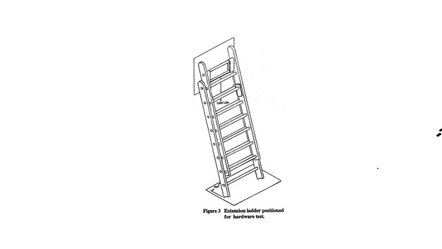
Last updated September 1, 2026 at 8:44 AM

Supplemental Information

Authorized By: 4121.12, 4121.121, 4121.13
Amplifies: 4121.13, Const. Art.II Section 35
Five Year Review Date: 9/1/2031
Prior Effective Dates: 1/1/2011, 10/1/2015
Rule 4123:1-21-06 | Fire hose, couplings, and nozzles.
 

(A) Care and use of attack hose, supply hose, and forestry hose.

(1) Large-diameter hose marked "Supply Hose" shall be used at operating pressures not to exceed one hundred eighty-five pounds per square inch (1275.5 kilopascals) to supply pumpers from hydrants and in relay from pumper to pumper and to directly supply attack lines, master streams appliances, portable hydrants, manifolds, and standpipe and sprinkler systems.

(a) If a higher operating pressure is needed, a hose having a service test pressure of at least ten per cent greater than the highest operating pressure shall be used.

(b) Six-inch (15.2 centimeters) supply hose shall not be used at operating pressures exceeding one hundred thirty-five pounds per square inch (930.8 kilopascals).

(2) A pressure and volume relief device with adequate capabilities and a maximum setting, not to exceed the service test pressure of the hose being used, shall be provided on the discharge side of the pump when large-diameter supply hose is being used to supply attack lines, manifolds, and standpipe and sprinkler systems.

(3) Rapid closing or opening valves shall not be used with large-diameter supply hose.

(4) When supply hose is used in relay between pumpers, the suction of each receiving pumper shall be equipped with a relief valve.

(5) Hose that has been frozen during use shall be thawed and service tested as specified in the most current edition of national fire protection association ("NFPA") 1930 before being put back in service or in storage.

(6) After use and before being placed in storage or back in service, the hose shall be drained, cleaned, and inspected as specified in paragraph (C) of this rule.

(B) Care and use of booster and hard suction hose.

(1) Booster and hard suction hose shall be service tested at least annually as specified in the most current edition of NFPA 1930.

(2) Hose which has exposed reinforcement shall be removed from service and repaired or destroyed. The defective section may be cut out, and the length recoupled and service tested as specified in the most current edition of NFPA 1930.

(C) The inspection, storage, and service test maintenance of fire hose, couplings, and nozzles shall comply with the most current edition of NFPA 1930.

Last updated September 1, 2026 at 8:44 AM

Supplemental Information

Authorized By: 4121.12, 4121.121, 4121.13
Amplifies: 4121.13, Construction Article II Section 35
Five Year Review Date: 9/1/2031
Prior Effective Dates: 1/1/1995
Rule 4123:1-21-07 | Fire department occupational safety and health.
 

(A) Incident management.

(1) An incident management system shall be established with written standard operating procedures applying to all employees involved in emergency operations.

(a) All employees involved in emergency operations shall be trained in the system.

(b) The incident management system shall be used at all emergency incidents.

(c) The incident management system shall be applied to drills, exercises, and other situations that involve hazards similar to those encountered at actual emergency incidents and to simulated incidents that are conducted for training and familiarization purposes.

(2) The incident management system shall use risk management based on the following principles:

(a) Activities that present a significant risk to the safety of employees shall be limited to situations where there is potential to save endangered lives.

(b) Activities that are routinely employed to protect property shall be recognized as inherent risks to the safety of employees, and actions shall be taken to reduce or avoid these risks.

(c) No risk to the safety of employees shall be acceptable when there is no possibility to save lives or property.

(3) The employer shall establish and ensure the maintenance of a fire dispatch and incident communication system.

(4) Each crew operating within the hazardous environment shall be provided with communication equipment capable of communicating with the incident command.

(B) Accountability.

(1) The employer shall establish written standard operating procedures for a personnel accountability system that provides for the tracking and inventory of all employees operating at an emergency incident. The system shall provide a rapid accounting of all personnel at the incident scene.

(2) The employer shall consider local conditions and characteristics in establishing the requirements of the personnel accountability system.

(3) Employees operating at an emergency incident shall actively participate in the personnel accountability system.

(4) The incident commander shall be responsible for overall personnel accountability for the incident. The incident commander shall initiate an accountability and inventory worksheet at the beginning of operations and shall maintain that system throughout the operations.

(C) Operating at emergency incidents.

(1) The employer shall provide an adequate number of personnel to safely conduct emergency scene operations. Operations shall be limited to those that can be safely performed by the employees available at the scene. No employee shall commence or perform any firefighting function or evolution that is not within the established risk management principles as specified in paragraph (A)(2) of this rule.

(2) Employees operating in hazardous environments at emergency incidents shall operate in teams of two or more.

Employees operating in hazardous environments shall be in communication with each other through visual, audible, or physical means, in order to coordinate their activities. Employees shall be in close proximity to each other to provide assistance in case of an emergency.

(3) In interior structural fires a minimum of four employees shall be required, consisting of two employees working as a team in the hazardous atmosphere, who shall remain in voice or visual contact with each other; and two employees who are located outside the hazardous atmosphere, who shall be responsible for maintaining a constant awareness of the number and identity of those operating in the hazardous atmosphere and be prepared to perform rescue of those employees if required. Interior structural firefighting means the physical activity of fire suppression, rescue, or both, inside of buildings or enclosed structures which are involved in a fire situation beyond the incipient stage.

(4) Initial attack operations shall be organized to ensure that, if upon arrival at the emergency scene, the initial attack employees find an imminent life-threatening situation where immediate action could prevent the loss of life or serious injury, such action shall be permitted with less than four employees. No exception shall be permitted when there is no possibility to save lives. Any such actions taken shall be thoroughly investigated by the employer.

(D) Operating at traffic incidents.

(1) The employer shall establish written standard operating procedures regarding emergency operations for traffic incidents.

(2) Fire apparatus shall be positioned in a blocking position to protect employees and other persons at the incident scene. When acting as a shield, fire apparatus emergency/warning lights shall remain on.

(3) All additional responding vehicles, when arriving on the scene, shall position beyond the traffic barrier unless their function requires placement before the barrier.

(4) At least five fluorescent orange traffic cones shall be used to warn oncoming traffic of the emergency operations and the hazards to employees operating at the incident.

The traffic cones shall not be less than twenty eight inches (71.1 centimeters) in height, each equipped with a six inch (15.2 centimeters) retro-reflective white band no more than four inches (10.2 centimeters) from the top of the cone, and an additional four inch (10.2 centimeters) retro-reflective white band two inches (5.1 centimeters) below the six inch (15.2 centimeters) band.

(5) When employees are operating at a traffic incident and their assignment places them in potential conflict with motor vehicle traffic, the employees shall wear garments that meet the requirements of the most current edition of American national standards institute and international safety equipment association ("ANSI/ISEA") 107, Class 2 or 3 "Standard for High - Visibility Safety Apparel," or public safety vests that meet the most current edition of ANSI/ISEA 107, "Standard for High - Visibility Public Safety Vests," with fluorescent and retro-reflective material.

(E) Risk management.

The employer shall develop and adopt a comprehensive written risk management plan. The risk management plan shall consider all fire department policies and procedures, and it shall include goals and objectives to ensure that the risks associated with the emergency and non-emergency operations of the fire department are identified and effectively managed.

(F) Employee fitness.

(1) The employer shall establish and provide a health and fitness program that meets the requirements of the most current edition of NFPA 1583 to enable employees to develop and maintain a level of fitness that allows them to safely perform their assigned functions.

(2) It shall be the responsibility of all employees to actively participate in the fitness and wellness program.

(3) The employer shall adopt written protocols to address occupational exposure to atypical stressful events that employees may experience in the course of their job duties.

(G) Infection control.

The employer shall operate an infection control program that meets the requirements of the most current edition of national fire protection association standard ("NFPA") 1581.

(1) Universal precautions shall be observed to prevent contact with blood or other potentially infectious materials. All body fluids shall be considered potentially infectious materials.

(2) The employer shall establish a written infectious and contagious disease "Exposure Control Plan" that includes universal precautions.

(3) Engineering and work practice controls shall be used to eliminate or minimize employee exposure.

(4) The employer shall make available, at no cost to the employee, the hepatitis B vaccine and vaccination series, including booster doses, to all employees who have potential occupational exposure.

(H) Hazardous materials.

The employer shall establish written plan that defines the employer's hazardous materials handling capabilities.

(1) The plan shall cover all hazardous material operations with all other responding agencies and their roles and capabilities.

(2) Employers shall develop and require use of a written plan covering the safe use, limitations, care, inspection, maintenance, and replacement of the hazardous materials equipment, and all affected employees shall be trained in accordance with the plan.

(I) Technical rescue.

The selection, care, and maintenance of personal protective equipment and associated technical equipment for technical rescue operations shall be as specified in the most current edition of NFPA 1855.

(1) Technical rescue operations are defined by the employers according to their risk management plan as defined in paragraph (E) of this rule.

(2) Employers shall develop and require use of a written plan covering the safe use, limitations, care, inspection, maintenance, and replacement of the equipment utilized in technical rescue operations, and all affected employees shall be trained in accordance of such plan.

Last updated September 1, 2026 at 8:44 AM

Supplemental Information

Authorized By: 4121.12, 4121.121, 4121.13
Amplifies: 4121.12, 4121.13, Construction Article II Section 35
Five Year Review Date: 9/1/2031
Prior Effective Dates: 11/1/2003